Correction of uneven image appearance by use of small-size data

a technology of image appearance and small size, applied in the field of display correction circuit and display apparatus, can solve the problems of uneven appearance, undefined shape, large size of data, etc., and achieve the effect of reducing the size of the rectangular region and reducing the uneven appearan

Inactive Publication Date: 2005-05-05
SHARP KK
View PDF5 Cites 32 Cited by
  • Summary
  • Abstract
  • Description
  • Claims
  • Application Information

AI Technical Summary

Benefits of technology

[0023] The rectangular region can approach a single point by reducing the size of the rectangular region. In the extreme case, the rectangular region is turned into a single point. In such a case, correction is such that its effect decreases toward an outer perimeter within a circle around the specified point. This makes it possible to properly correct a circular uneven appearance. Alternatively, a finite rectangular region may be specified, with the width of the surrounding being set to zero, thereby providing for the correction of a rectangular region. This successfully corrects a shot uneven appearance. The width of the rectangular correction region may be set substantially equal to one line, providing for a streak uneven appearance to be properly corrected. An extension from one edge of the screen to an opposite edge of the screen may be specified to correct a band uneven appearance.
[0024] Further, the gray levels for correction may be provided in 512 levels (i.e., 9-bit representation) to achieve the representation of fine brightness. This makes it possible to properly reduce uneven appearance even at a portion where density is low.

Problems solved by technology

In the liquid crystal display apparatuses, for example, such uneven image appearance is caused by variation in the thickness of liquid crystal display cells, the thickness of electrode patterns, etc.
A circular uneven appearance has a circular shape appearing on the screen, and is caused by a locally different cell thickness (thinner or thicker) than surrounding areas, local abnormality of TFT characteristics, local abnormality of electrode pattern size, the presence of a pinhole in the orientation layer, the inadvertent mixing of tarnishing foreign material, etc.
In addition to those uneven appearances as described above, there are uneven appearances having undefined shape that is difficult to describe in word.
In Patent Document 1, the size of data becomes enormous as the area of uneven appearance increases.
In reality, however, a function for correction needs to be specified with respect to the spread of uneven appearance from the center in each direction, resulting in a large number of required parameters.
Further, although this method can remove an uneven appearance having a circular or ellipse shape, uneven appearances of non-circular shape such as a band uneven appearance, a frame uneven appearance, a streak uneven appearance, a shot uneven appearance, etc., cannot be removed.
Moreover, 8-bit data cannot properly represent the periphery of uneven appearance or the like where unevenness is extremely thin.
Further, addition of a correction circuit for removing uneven appearance results in a cost increase of a controller IC.
The possibility of having uneven appearance is rather small relative to a total manufacturing quantity.
Business is not profitable unless economical loss caused by the disposal of a defective unit exceeds 50,000 yen.

Method used


Image

  • Correction of uneven image appearance by use of small-size data
  • Correction of uneven image appearance by use of small-size data
  • Correction of uneven image appearance by use of small-size data

Examples


Embodiment Construction

[0040] In the following, embodiments of the present invention will be described with reference to the accompanying drawings.

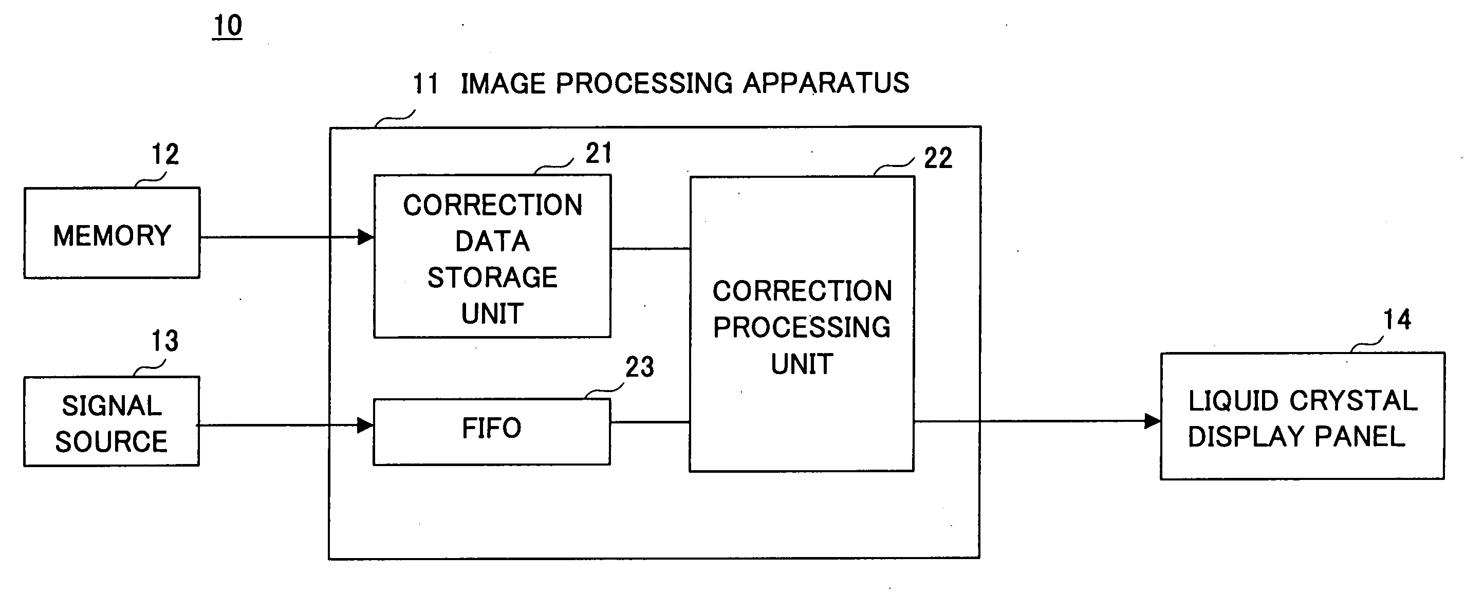
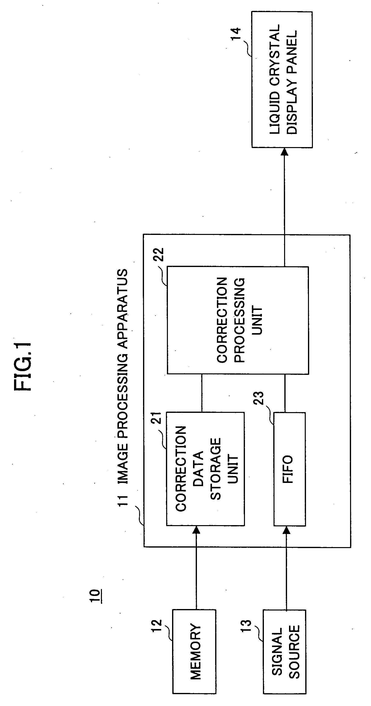
[0041]FIG. 1 is a block diagram showing an example of the construction of a liquid crystal display apparatus according to the invention. Although a description will be given here with reference to the liquid crystal display apparatus of FIG. 1, it should be noted that the invention is equally applicable to other types of display apparatuses such as a plasma display apparatus.

[0042] A liquid crystal display apparatus 10 of FIG. 1 includes an image processing apparatus 11, a memory 12, a signal source 13, and a liquid crystal display panel 14. The memory 12 stores correction data for use in the correction of uneven appearance. The signal source 13 supplies image data signals for display on the liquid crystal display panel 14. The image processing apparatus 11 corrects the image data signals supplied from the signal source 13 based on the correction data supplie...


PUM

PropertyMeasurementUnit
sizeaaaaaaaaaa
widthaaaaaaaaaa
brightnessaaaaaaaaaa

Abstract

A circuit for display correction includes a memory which stores first data indicative of size and position of a rectangular region on a display screen and second data indicative of gray level changes in a surrounding region around the rectangular region in an isometric manner with respect to a horizontal direction and a vertical direction, and an image processing unit which adjusts gray levels of image data in response to the first data and the second data stored in the memory.

Description

BACKGROUND OF THE INVENTION [0001] 1. Field of the Invention [0002] The present invention generally relates to display correction circuits and display apparatuses, and particularly relates to a display correction circuit and a display apparatus which correct uneven image appearance caused by the characteristics of the display apparatus. [0003] 2. Description of the Related Art [0004] In liquid crystal display apparatuses, plasma display apparatuses, or the like, uneven image appearance may be observed when display brightness becomes darker or brighter, for example, than desired brightness at some places on the screen. In the liquid crystal display apparatuses, for example, such uneven image appearance is caused by variation in the thickness of liquid crystal display cells, the thickness of electrode patterns, etc. [0005] A circular uneven appearance has a circular shape appearing on the screen, and is caused by a locally different cell thickness (thinner or thicker) than surrounding...

Claims


Application Information

Patent Timeline
Patent Type & Authority Applications(United States)
IPC IPC(8): G02F1/133G09G3/20G09G3/36G09G5/00G09G5/02H04N5/57H04N5/66
CPCG09G3/20G09G3/2007H04N5/57G09G2320/0233G09G2320/0285G09G3/3611G01R31/44
Inventor KAMADA, TSUYOSHINUKIYAMA, KAZUHIROSUZUKI, TOSHIAKI
Owner SHARP KK
Why Eureka
Try Eureka