Mops and mop components

a technology of mop components and mops, which is applied in the field of mops, can solve the problems of reducing affecting the service life of the absorbent member, and requiring substantial physical effort to compress the absorbent member,

Inactive Publication Date: 2005-02-10
FREUDENBERG HOUSEHOLD PROD LP
View PDF7 Cites 32 Cited by
  • Summary
  • Abstract
  • Description
  • Claims
  • Application Information

AI Technical Summary

Benefits of technology

[0008] Preferably, the wringing mechanism is configured somewhat comparably to that of the mop disclosed in prior U.S. patent application Ser. No. 09/514,711. In this respect, the wringing mechanism includes an operator handle, a channel body, and an actuator link. The operator handle is movably mounted to the shaft. The channel body is disposed at the cleaning end of the shaft and includes first and second legs which define a channel therebetween. The actuator link is connected to the operator handle and one of the mop element and the channel body. The channel body and mop element are disposed in a relatively hinged relationship with respect to one another along a hinge line lying along or parallel to the longitudinal axis of the mop element. The mop element and the channel body are relatively movable over a range of travel. Movement of the handle in a wringing direction effects relative hinged movement of the mop element and the channel body. The liquid absorbent member is drawn into

Problems solved by technology

A problem with conventional butterfly mops is the difficulty inherent in manually applying sufficient force to the actuating mechanism to fold the liquid absorbent member over onto itself and to compress the liquid absorbent member sufficiently to satisfac

Method used


Image

  • Mops and mop components
  • Mops and mop components
  • Mops and mop components

Examples


Embodiment Construction

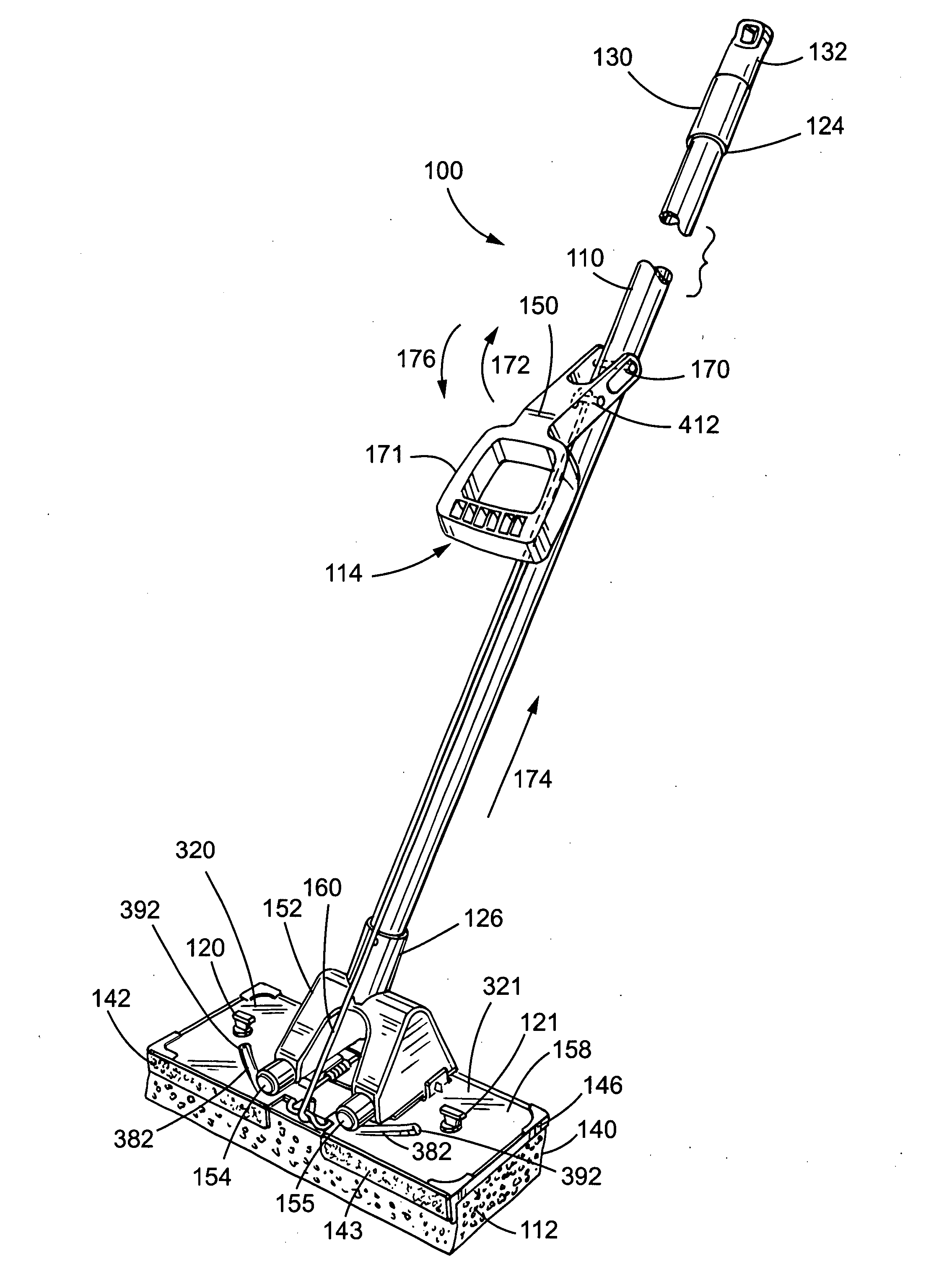
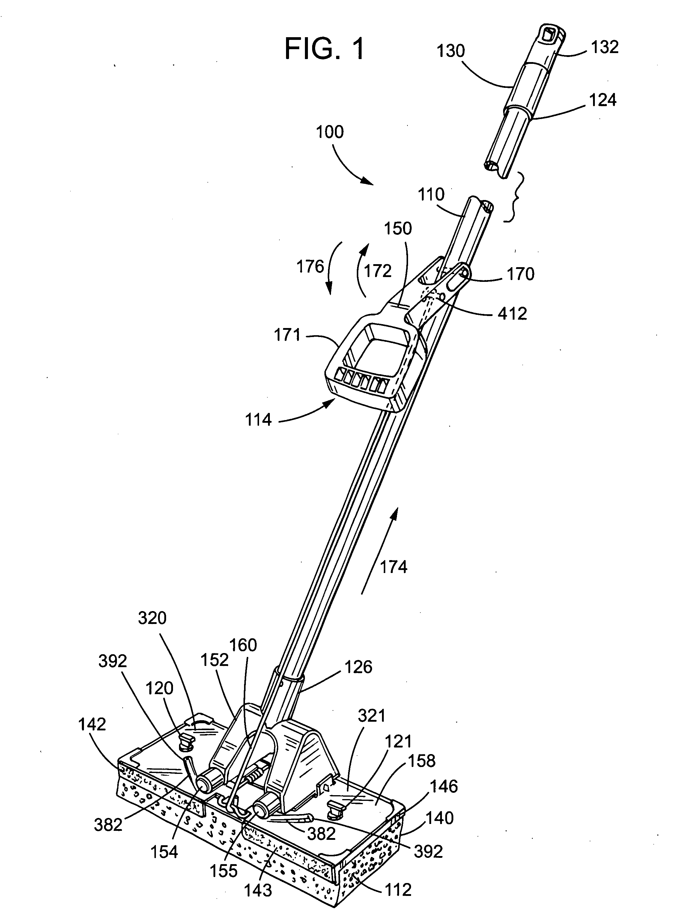
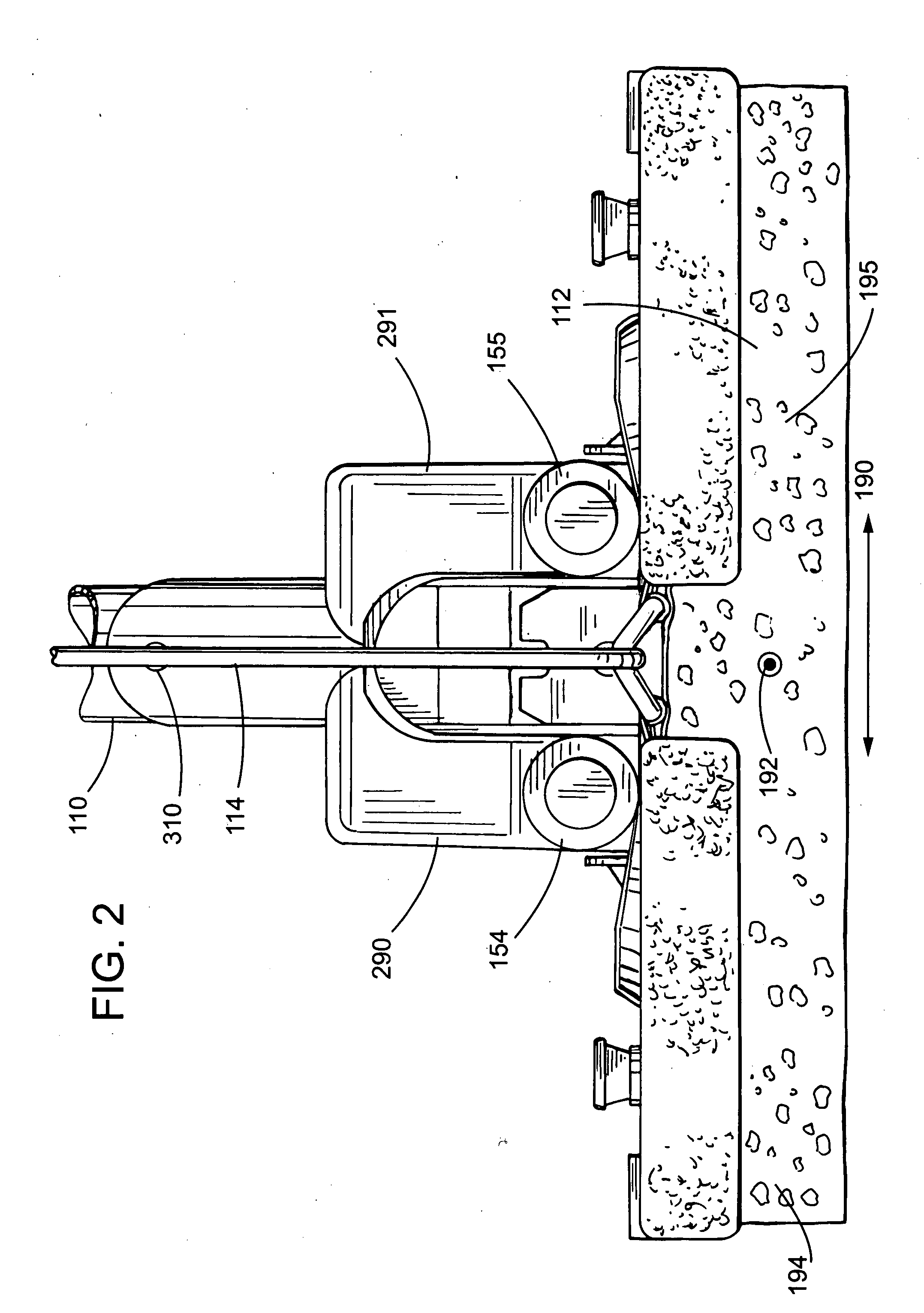
[0048] Referring to FIG. 1, a butterfly mop 100 according to the present invention generally includes an elongate shaft 110, a mop element 112, and a wringing mechanism 114 that is connected to the shaft 110 and to the mop element 112. The shaft includes an operator end 124 and a cleaning end 126 which define a longitudinal axis. A hanging cap 130 is disposed at the operator end of the shaft 110. To facilitate mounting the mop, at least a portion 132 of the hanging cap can rotate with respect to the shaft about an axis that is collinear with the longitudinal axis of the shaft.

[0049] The mop element 112 is disposed at the cleaning end 126 of the shaft and is secured to a mop element support 158 of the wringing mechanism 114. The mop element 112 may comprise solely a compressible, elongate liquid absorbent member 140, but preferably comprises an assembly that further includes a pair of scrubber members 142, 143, and a mounting element 146 for supporting the liquid absorbent member an...


PUM


Abstract

Disclosed is a butterfly mop having an elongate shaft with a mop element disposed at one end of the shaft and a wringer connected to the shaft and the mop element. In preferred embodiments, the wringer includes a channel body having first and second leg portions defining a channel therebetween. The mop element includes a foldable, compressible, liquid-absorbent member, a mounting element having first and second support portions connected by a flexible member, and a scrubber mounted to the mounting element. The mop element and channel body are movable relative to one another, whereby the mop element may be drawn into the channel causing the mop element to fold along a central transverse axis and to become compressed between the channel body leg portions. The wringer includes a handle and an actuator link connecting the handle to one of the mop element and channel body for effecting relative hinged movement thereof. In some embodiments, the mop element includes a support that has first and second support portions and a flexible member connecting the first and second support portions. In certain embodiments, a fastener having a barbed shaft is used to connect the mop element to the wringing mechanism of the mop.

Description

TECHNICAL FIELD OF THE INVENTION [0001] The present invention is directed toward mops, and more specifically, is in the field of butterfly mops. BACKGROUND OF THE INVENTION [0002] Butterfly mops are characterized in that they comprise an elongate, foldable, compressible, liquid-absorbent member, such as a sponge, which is disposed at one end of a mop shaft, and which is used to absorb liquid, typically water, from a surface. When it is desired to expel liquid from the absorbent member, portions of the absorbent member are folded over one another along a transverse axis of the absorbent member and are compressed, using a folding mechanism such as a roller or track. Butterfly mops are so named because the folding and unfolding of the absorbent member along its transverse axis is said to resemble the motion of the wings of a butterfly. [0003] One typical butterfly mop is shown in U.S. Pat. No. 2,892,201. As shown therein, the butterfly mop includes a liquid absorbent member, two plates...

Claims


Application Information

Patent Timeline
IPC IPC(8): A47L13/146
CPCA47L13/146
Inventor BOYER, CHRISVUCKOVIC, MIROSLAV
Owner FREUDENBERG HOUSEHOLD PROD LP
Why Eureka
Try Eureka