Battery pack

a battery pack and battery technology, applied in the field of batteries, can solve the problems of difficult to confirm the connection of lead plate and battery, limit the maximum output, and easily disconnect plates and batteries during lead plate bending, etc., and achieve the effect of low resistance, low resistance, and low resistan

Active Publication Date: 2005-02-10
SANYO ELECTRIC CO LTD
View PDF6 Cites 109 Cited by
  • Summary
  • Abstract
  • Description
  • Claims
  • Application Information

AI Technical Summary

Benefits of technology

[0010] The battery pack described above has the characteristic that a plurality of batteries can be connected in an extremely low resistance configuration. This is because lead plates are connected to a plurality of battery terminals to form parallel units, and a plurality of parallel units are also connected in series by these lead plates. In particular, the battery pack connects a plurality of battery terminals together with a single lead plate to connect these batteries in parallel and in series. The lead plates of a battery pack of this structure do not bend in two as in prior art battery packs. Instead, batteries connected in parallel can be connected in series by wide lead plates. Consequently, a plurality of batteries can be connected in a low resistance series configuration without reducing the resistivity of the series connected region.
[0011] Since the battery pack described above does not bend lead plates in two as in prior art battery packs but rather connects a plurality of batteries

Problems solved by technology

This is because high currents result in large losses even with extremely small electrical resistance, and consequently this limits maximum output.
The battery pack shown In FIGS. 1 and 2 has the further drawback that since lead plates connected to the terminals of all the batteries are bent 180° and connected to the circuit board, lead plates and batteries can easily become disconnected during lead plate bending.
In addition, a lead plate may not be completely disconnected from a battery, but ma

Method used


Image

  • Battery pack
  • Battery pack
  • Battery pack

Examples


Embodiment Construction

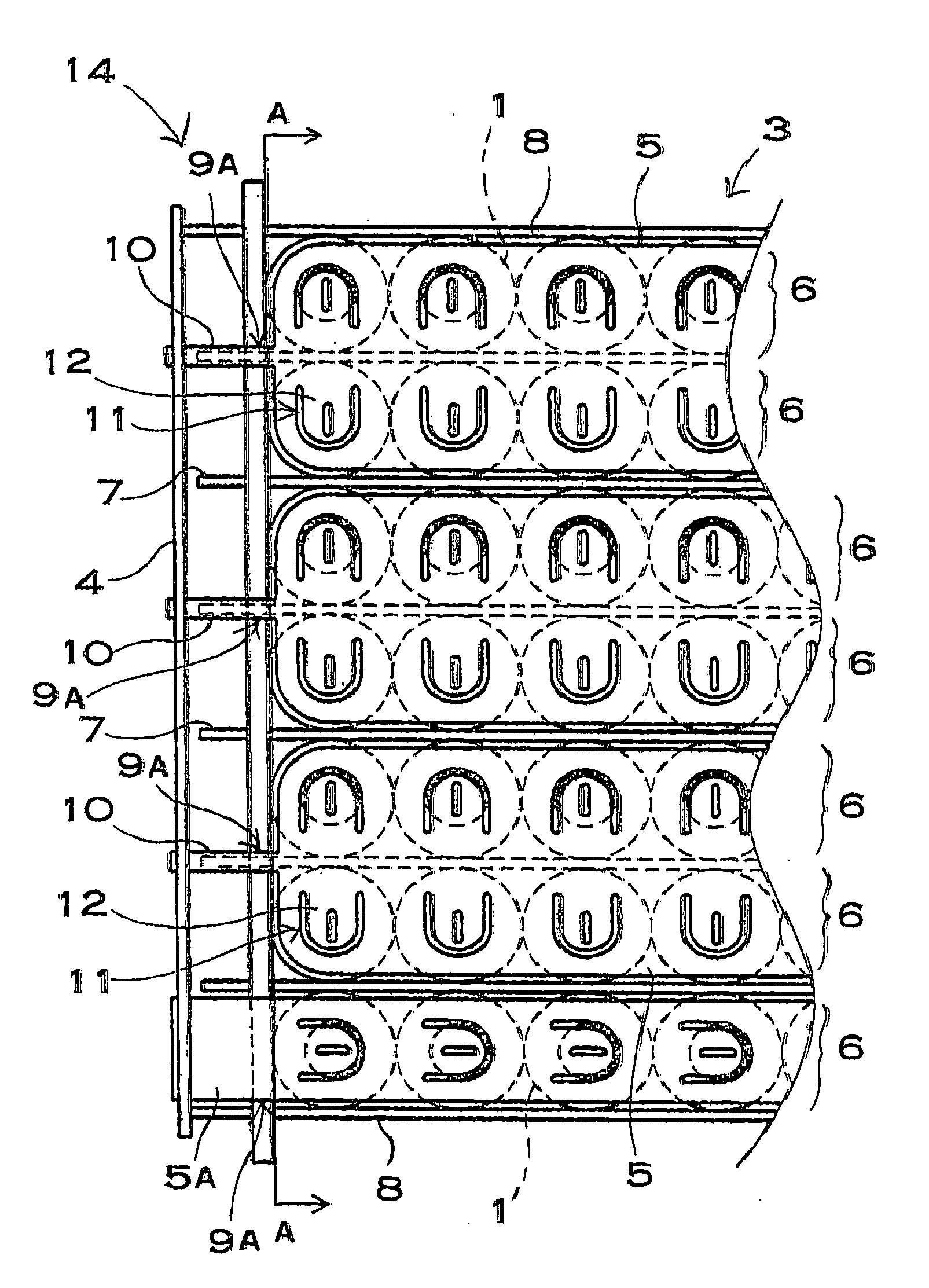
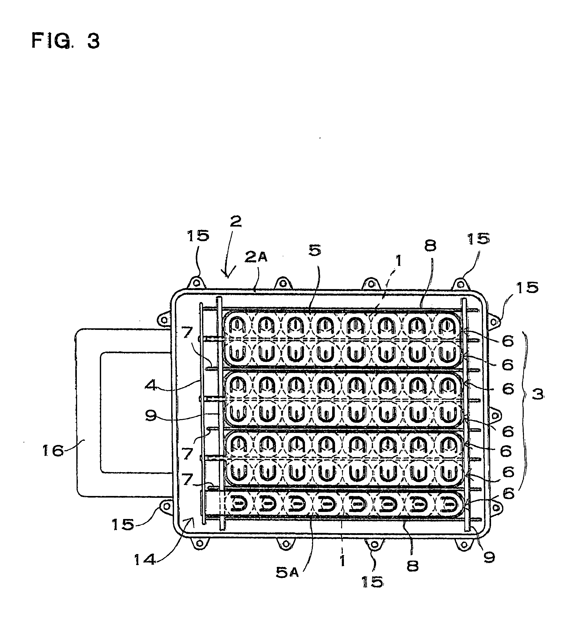
[0026] The battery pack shown in FIG. 3 is provided with a battery block 3 which is a plurality of batteries 1 arranged vertically and horizontally in mutual proximity and oriented perpendicular to a specified plane of the case 2 (a plane parallel to the paper in FIG. 3), a case 2 which houses the battery block 3, and a circuit board 4 which is connected with the batteries 1.

[0027] Batteries 1 of the battery block 3 which are lined up in a horizontal row (left-right direction in FIG. 3) are aligned with the same orientation. In addition, lead plates 5 are connected to the terminals of batteries 1 lined up with the same orientation to connect a plurality of batteries 1 in parallel and form parallel units 6. Further, as shown in FIGS. 3-5, a plurality of parallel units 6 are arranged in the vertical direction (up-down direction in the figures) of the battery block 3 with different orientations. Finally, as shown in FIG. 5, battery 1 terminals of vertically adjacent parallel units 6 a...


PUM


Abstract

The battery pack is provided with a battery block, a case, and a circuit board. The battery block has a plurality of batteries lined up in a horizontal row with the same orientation, and lead plates connect to terminals of those batteries to form a parallel unit. A plurality of parallel units are stacked in the vertical direction with different orientation, and battery terminals are connected by lead plates in the vertical direction to connect parallel units in series. Lead plates have projections which protrude horizontally beyond the confines of the battery block and connect with the circuit board, and the battery block and circuit board are connected as a unit.

Description

BACKGROUND OF THE INVENTION [0001] This invention relates primarily to a battery pack suitable for high current discharges, and in particular to a battery pack with a plurality of batteries connected in series and parallel. [0002] Battery pack output current can be increased by increasing the number of batteries connected in parallel, and battery pack output voltage can be increased by increasing the number of batteries connected in series. From this, battery packs used in applications requiring large output, such as bicycles, tools, and automobiles, can increase output by connecting a plurality of batteries in parallel, and again connecting those units in series. Since many batteries are housed in this type of battery pack, a configuration which allows efficient connection of each battery is important. As an implementation of this, a battery pack has been developed with batteries connected by a uniquely structured lead plate (patent reference 1). Patent reference 1 is Japanese pate...

Claims


Application Information

Patent Timeline
IPC IPC(8): H01M10/42H01M10/48H01M50/528H01M50/503H01M50/505H01M50/512H01M50/516H01M50/529H01M50/569H01M50/588H01M50/593
CPCH01M2/202H01M2/24H01M10/482H01M10/4257H01M2/34Y02E60/10H01M50/529H01M50/588H01M50/516H01M50/512H01M50/593H01M50/505H01M50/503H01M50/569
Inventor MORITA, HIDEYOMIZUTA, KATSUJI
Owner SANYO ELECTRIC CO LTD
Why Eureka
Try Eureka