Battery assembly and method of making same

a battery and assembly technology, applied in the field of batteries, can solve the problems of inability to form a battery using more than three cells, terminals are more prone to failure, and the simple structure of batteries is inadequa

Inactive Publication Date: 2005-02-10
DYNAVAIR LLC
View PDF9 Cites 120 Cited by
  • Summary
  • Abstract
  • Description
  • Claims
  • Application Information

AI Technical Summary

Problems solved by technology

Simple structures for batteries are inadequate, however, when the environment in which a battery is placed is hostile.
Increasing the stress levels in the terminals makes the terminals more prone to failure due to vibration and corrosion.
In addition, the ability to form a battery using more than three cells is greatly inhibited due to the limitation of the ultrasonic welding process.

Method used


Image

  • Battery assembly and method of making same
  • Battery assembly and method of making same
  • Battery assembly and method of making same

Examples


Embodiment Construction

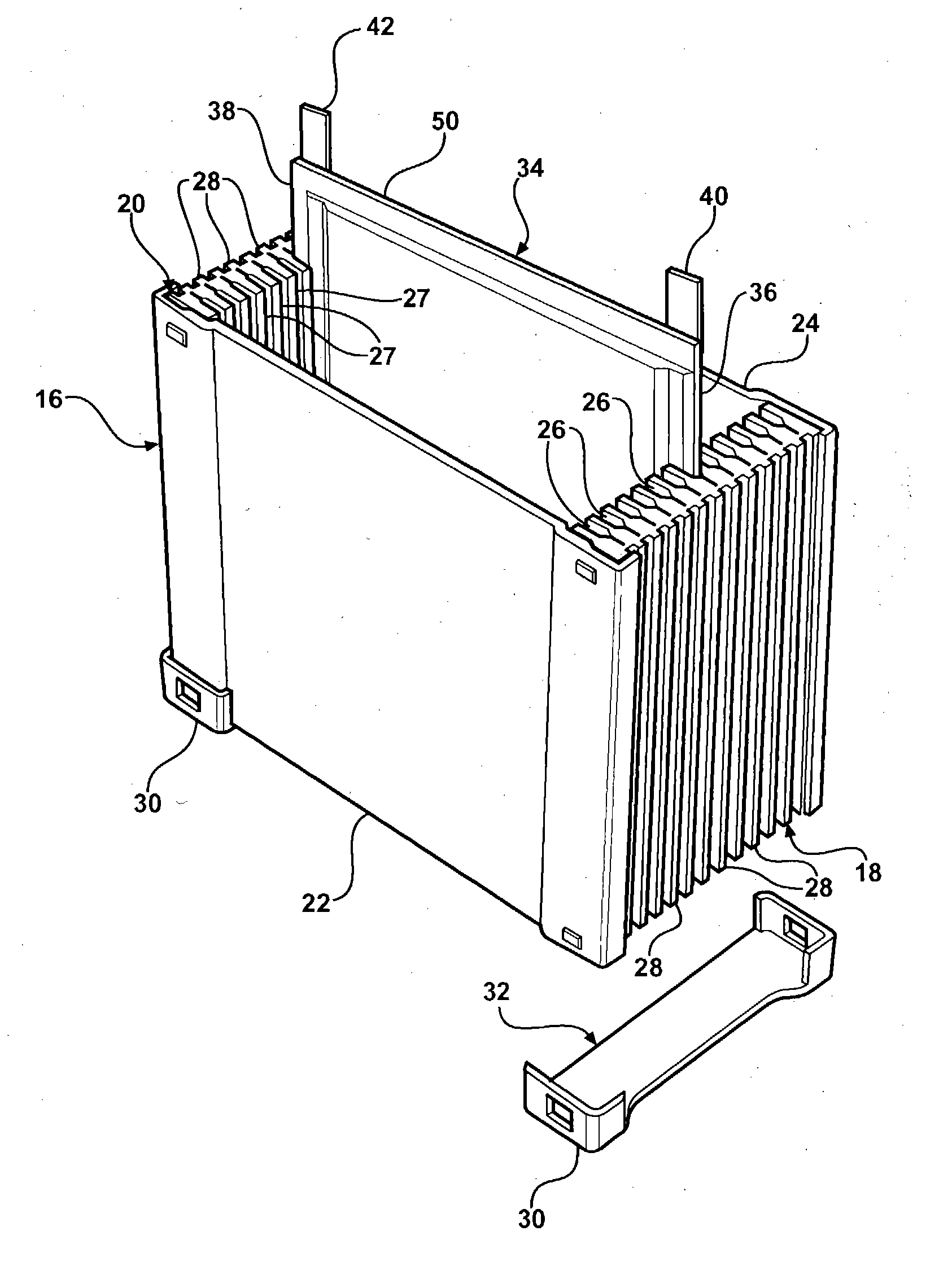
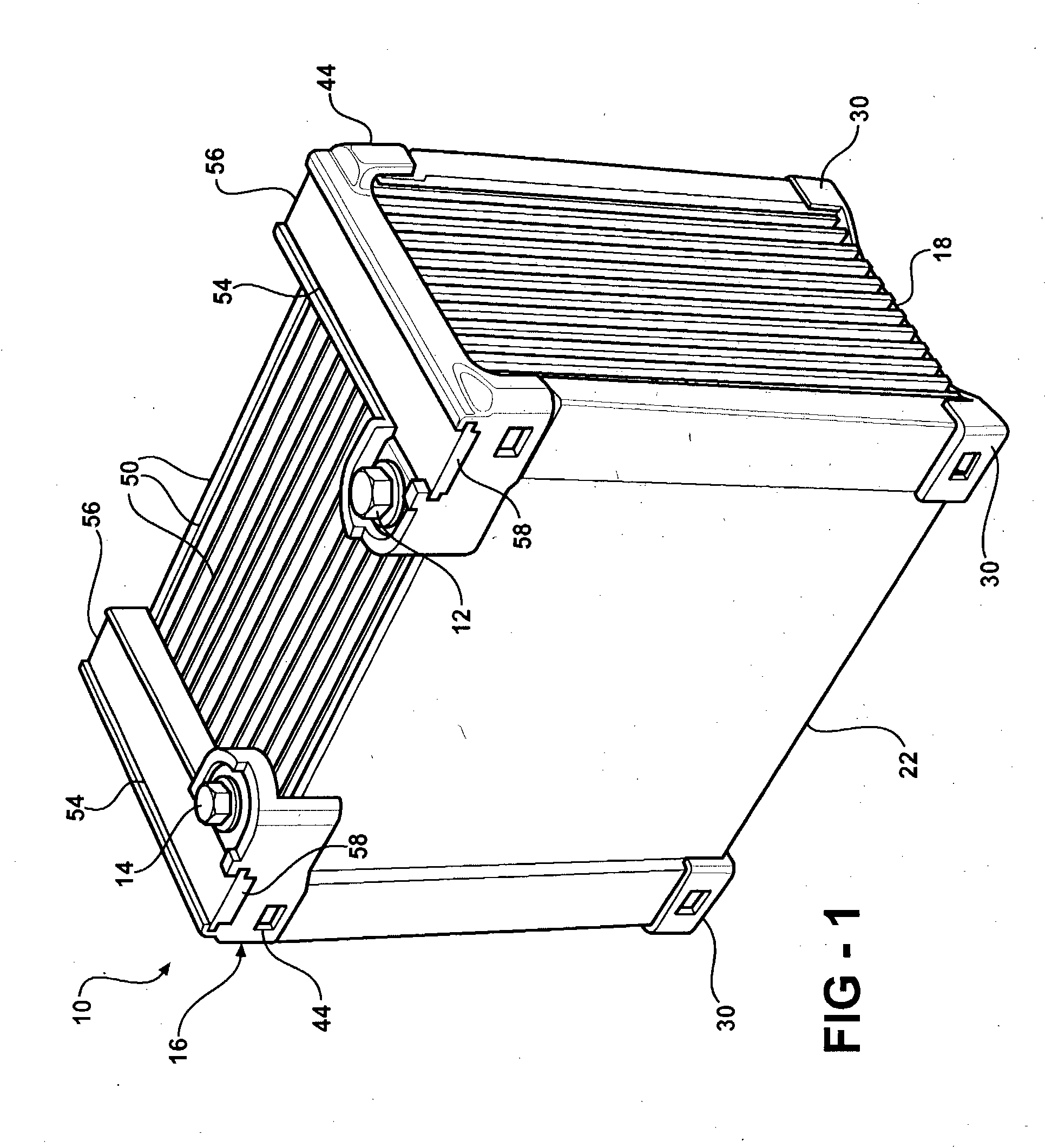
[0018] Referring to FIG. 1, a battery assembly is generally indicated at 10. The battery assembly 10 stores electrical energy and releases this energy through an electrical current to a circuit that is connected to each of the two battery posts 12, 14 that act as terminals for the battery. The battery posts 12, 14 are shown as bolts that provide an electrical path to an electrical conductor, discussed subsequently, wherein the bolts are threadingly secured to the electrical contact so that an electrical circuit may be secured thereto by tightening the bolts of the battery posts 12, 14 forcing a physical, electrical connection therebetween.

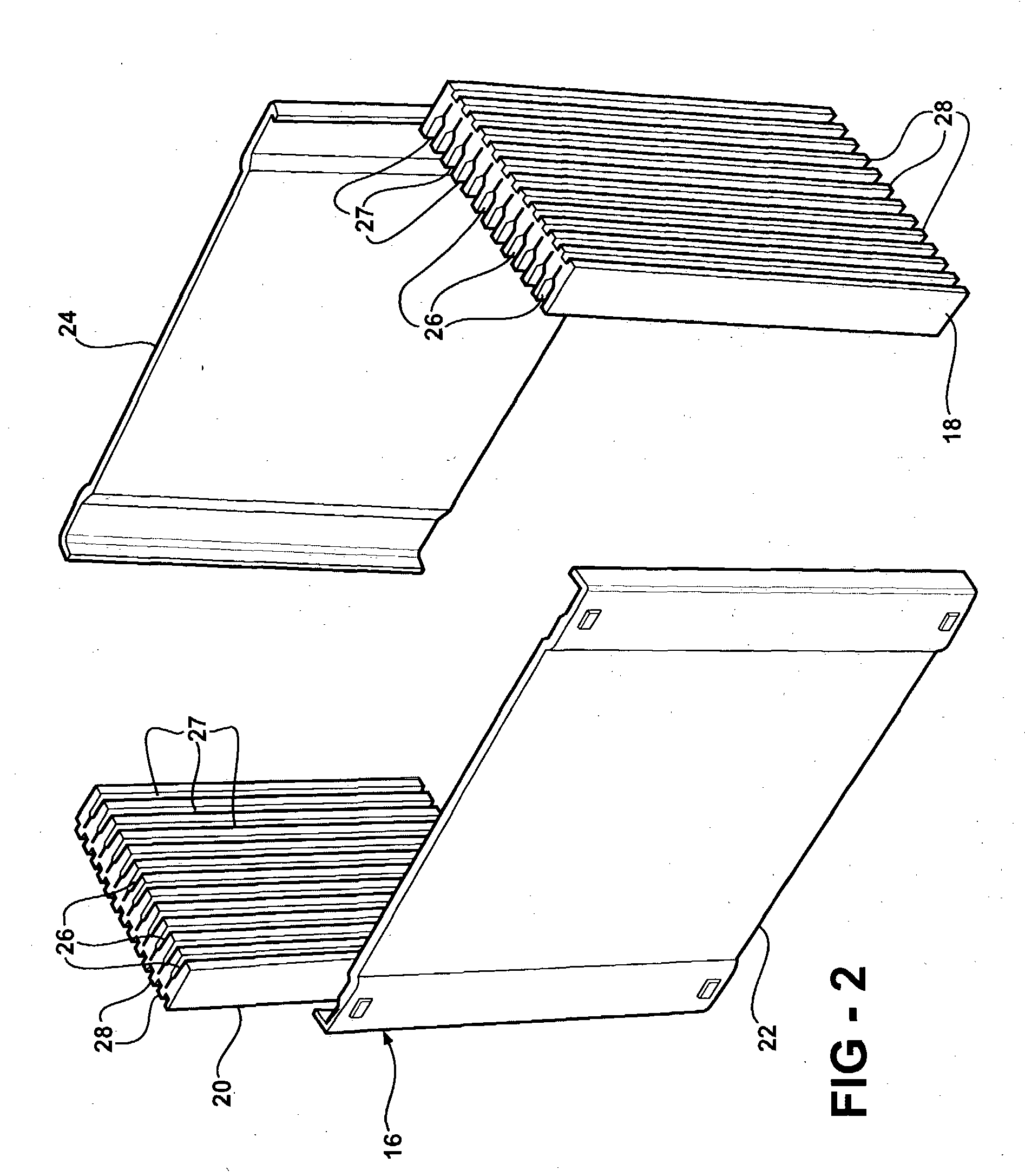
[0019] The battery assembly 10 includes a frame, generally shown at 16. The frame 16 includes a pair of end supports 18, 20 and a pair of side supports 22, 24. In particular, a front side support 22 extends across a front of the battery assembly 10 between the two end supports 18, 20 at one end thereof and a back side support 24 extends across the...


PUM

PropertyMeasurementUnit
electric energyaaaaaaaaaa
electric potentialaaaaaaaaaa
angleaaaaaaaaaa

Abstract

A battery assembly is designed to include a plurality of cells positioned parallel to each other. A frame including end supports position the cells appropriately. Each of the cells includes a first terminal and a second terminal. Two buses are positioned over all of the first terminals and all of the second terminals. Each of the buses includes slots allowing the terminals to extend therethrough. Once through, the terminals are bent over the bus bar. A slide is then positioned over the terminals protecting the terminals and maintaining the terminals in electrical contact with each other. This battery assembly allows more than three cells to be connected to each other and is versatile enough to allow the removal of certain cells to enhance the airflow through the battery assembly.

Description

BACKGROUND ART [0001] 1. Field of the Invention [0002] The invention relates to a battery. More particularly, the invention relates to a battery being fabricated of component parts and a method for assembling same. [0003] 2. Description of the Related Art [0004] Batteries are fabricated by combining a number of individual cells together. Batteries are a collection of cells connected in parallel and / or series. When the battery is to be used with a stationary device, merely connecting the terminals and allowing the cells to sit side by side in a simple structure is adequate. [0005] Simple structures for batteries are inadequate, however, when the environment in which a battery is placed is hostile. Examples of hostile environments include elements of extreme temperature changes, humidity, and vibration, all of which are typically found in automobiles, aircraft, watercraft and the like. These batteries require a structure to support the cells in relation to each other. In addition, the...

Claims


Application Information

Patent Timeline
Patent Type & Authority Applications(United States)
IPC IPC(8): H01M50/211H01M50/528H01M50/529H01M50/55H01M50/557
CPCH01M2/0212H01M2/266H01M2/22H01M2/1061Y02E60/10H01M50/557H01M50/528H01M50/55H01M50/211
Inventor KRUGER, DUANE D.BEER, ROBERT C.
Owner DYNAVAIR LLC
Why Eureka
Try Eureka