
Hinge

a technology of lubricant and spherical rods, applied in the field of spherical rods, can solve problems such as polluting notebooks, and achieve the effect of preventing lubricant from leaking

Inactive Publication Date: 2005-02-17
WU CHING SUNG
View PDF25 Cites 25 Cited by
  • Summary
  • Abstract
  • Description
  • Claims
  • Application Information

AI Technical Summary

Benefits of technology

[0007] The main objective of the present invention is to provide an improved hinge that can prevent the lubricant from leaking.
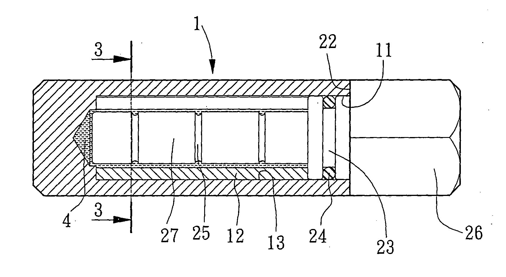
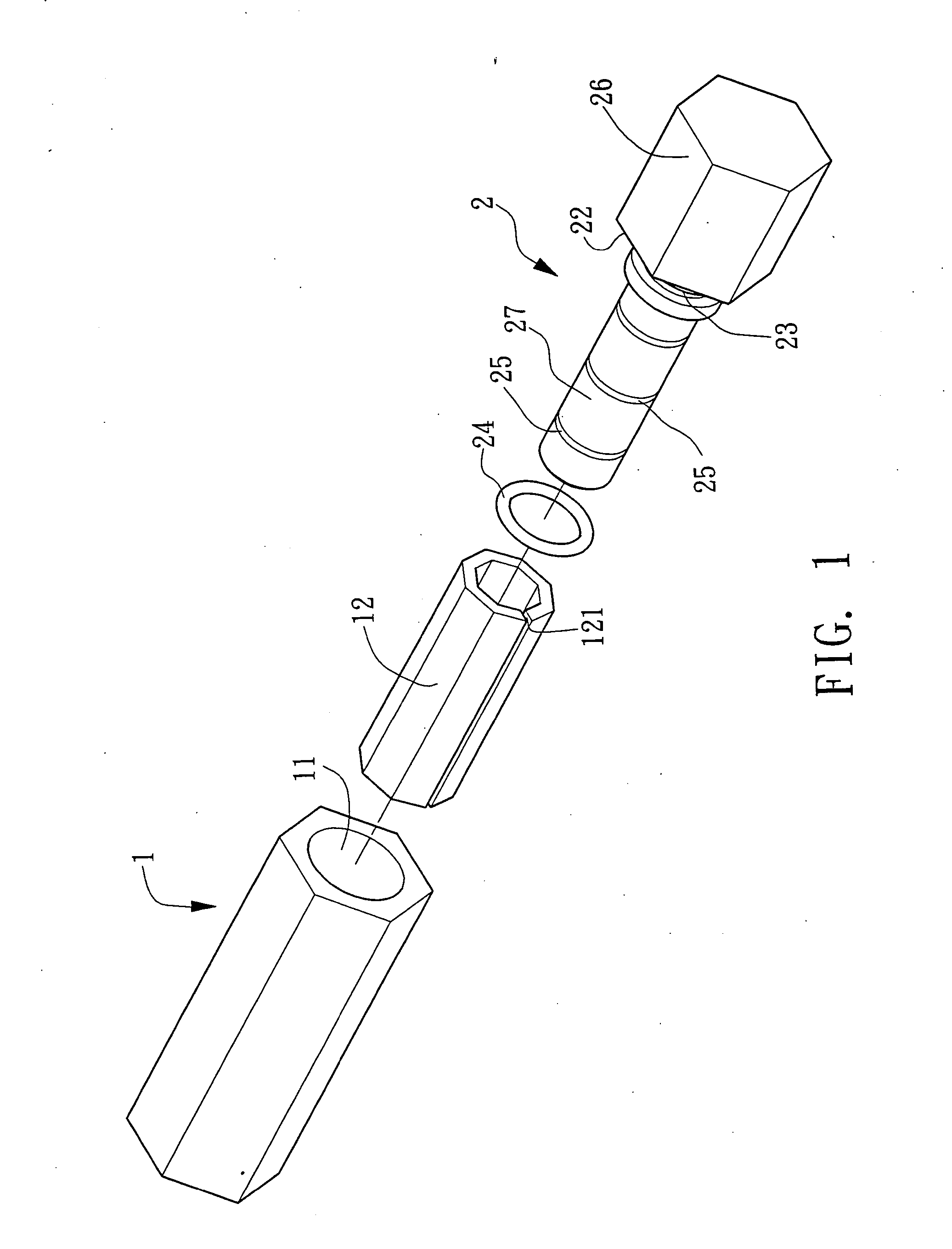
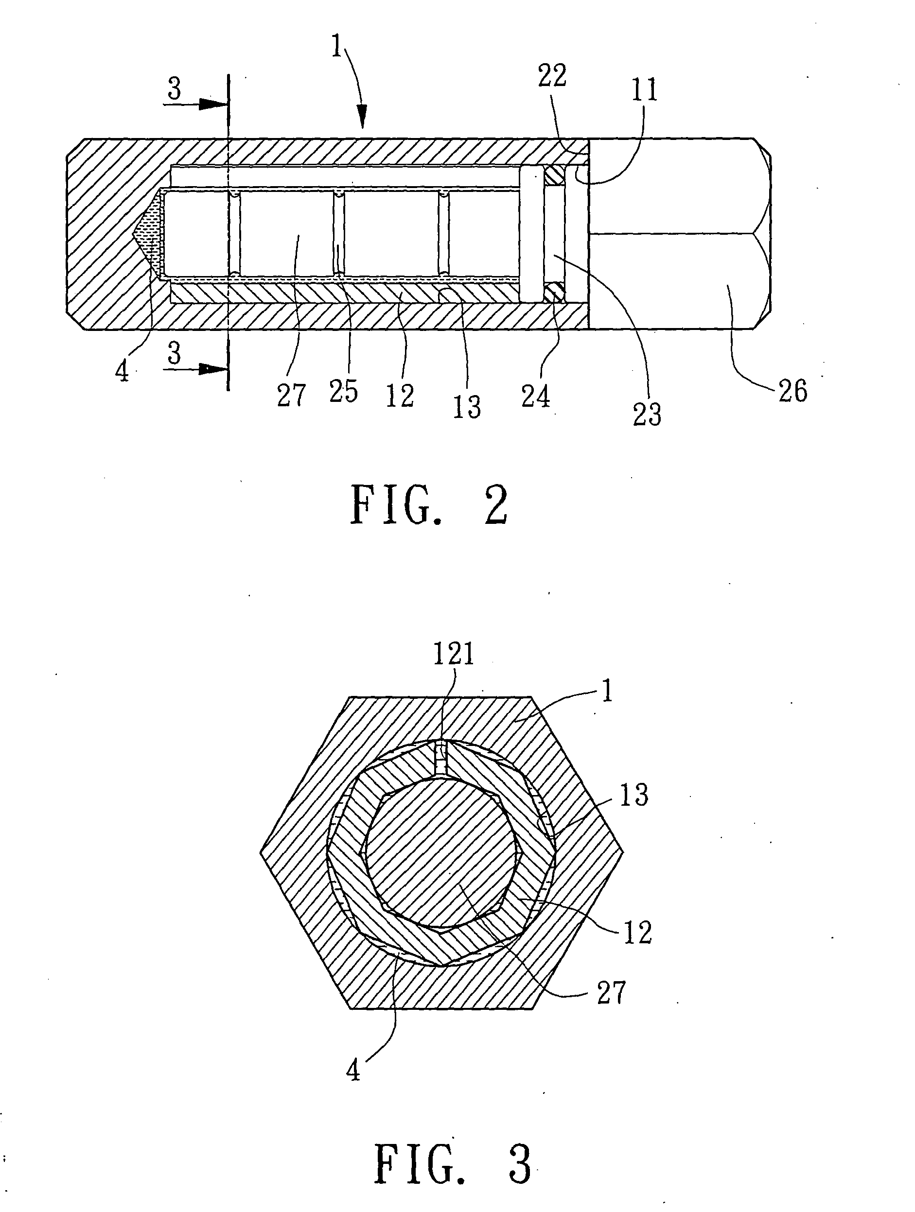
[0008] To achieve the objective, the hinge in accordance with the present invention comprises a cylinder having a close end and an open end longitudinally opposite to the close end of the cylinder. A polygonal sleeve is fixedly received in the cylinder. The polygonal sleeve has multiple edges abutting against an inner periphery of the cylinder. A pivot axle is partially pivotally received in the sleeve. A sealant is mounted around the pivotally for tightly closing the open end of the cylinder to prevent the lubricant in the hinge from leaking.

Problems solved by technology

Furthermore, the leaking lubricant (7) may pollute the notebook.

Method used


Image

  • Hinge
  • Hinge
  • Hinge

Examples


Embodiment Construction

[0019] Referring to the drawings and initially to FIGS. 1-3, a hinge in accordance with the present invention comprises a cylinder (1), a sleeve (12) fixedly and fully received in the cylinder (1) and a pivot axle (5) partially pivotally received in the sleeve (12).

[0020] The cylinder (1) includes a close end adapted to be secures on an object and an open end longitudinally opposite to the close end of the cylinder (1). The sleeve (12) has a polygonal shape. In the preferred embodiment of the present invention, the sleeve (12) is octagonal. The sleeve (12) has multiple edges abutting an inner periphery (13) of the cylinder (1) due to the pivot axle (2) partially inserted into the sleeve (12). The sleeve (12) has a slit (121) defined in an outer periphery of the sleeve (12) and extending through the sleeve (12). The pivot axle (2) includes an enlarged head (26) adapted to be secured on an object and a shank (27) centrally longitudinally extending from the enlarged head (26). The sha...


PUM


Abstract

A hinge includes a cylinder having a close end and an open end longitudinally opposite to the close end of the cylinder. A polygonal sleeve is fixedly received in the cylinder. The polygonal sleeve has multiple edges abutting against an inner periphery of the cylinder. A pivot axle is partially pivotally received in the sleeve. A sealant is mounted around the pivotally for tightly closing the open end of the cylinder to prevent the lubricant in the hinge from leaking.

Description

BACKGROUND OF THE INVENTION [0001] 1. Field of the Invention [0002] The present invention relates to a hinge, and more particularly to a hinge that can prevent the lubricant from leaking. [0003] 2. Description of Related Art [0004] A conventional hinge, usually used to a notebook, in accordance with the prior art shown in FIG. 7 comprises a sleeve (5) and a pivot axle (6) partially pivotally received in the sleeve (5). The sleeve (5) includes a slit (51) defined in an outer periphery of the sleeve (5) and extending through the slit (5) such that the sleeve (5) can be slight shrunk due to the slit (51). A plate (52) longitudinally extends from the sleeve (5) opposite to the pivot axle (6). The plate (52) is adapted to be secured on the notebook. The pivot axle (5) includes a rod (61) centrally and longitudinally extending therefrom opposite to the sleeve (5). The rod (61) is adapted to be secured on a monitor of the notebook. Consequently, the monitor can be circuitously moved relati...

Claims


Application Information

Patent Timeline
IPC IPC(8): E05D11/02E05D11/08G06F1/16
CPCE05D11/02E05D11/082Y10T16/54038G06F1/1616G06F1/1681E05Y2900/606E05Y2999/00
Inventor WU, CHING SUNG
Owner WU CHING SUNG
Learn More