Anti-drawback medical valve
a technology of anti-drawback and medical valves, applied in the field of medical valves, can solve the problems of blood being drawn proximally into the valve, compromising the sterility of the valve, and the blood in the valve (or in the catheter) also compromising the sterility
- Summary
- Abstract
- Description
- Claims
- Application Information
AI Technical Summary
Benefits of technology
Problems solved by technology
Method used
Image
Examples
second embodiment
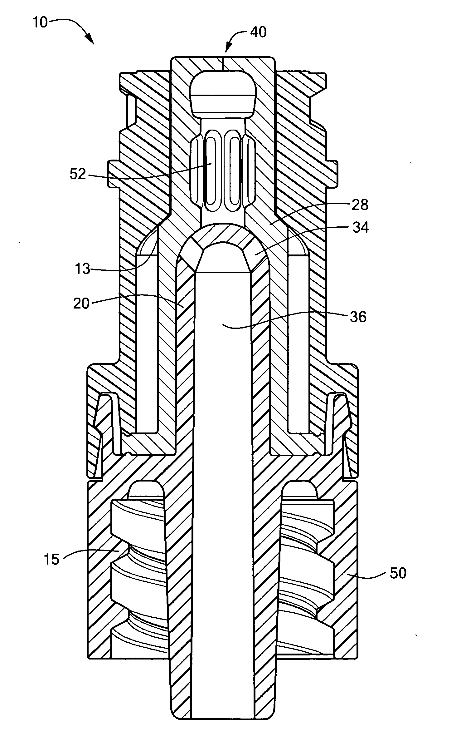
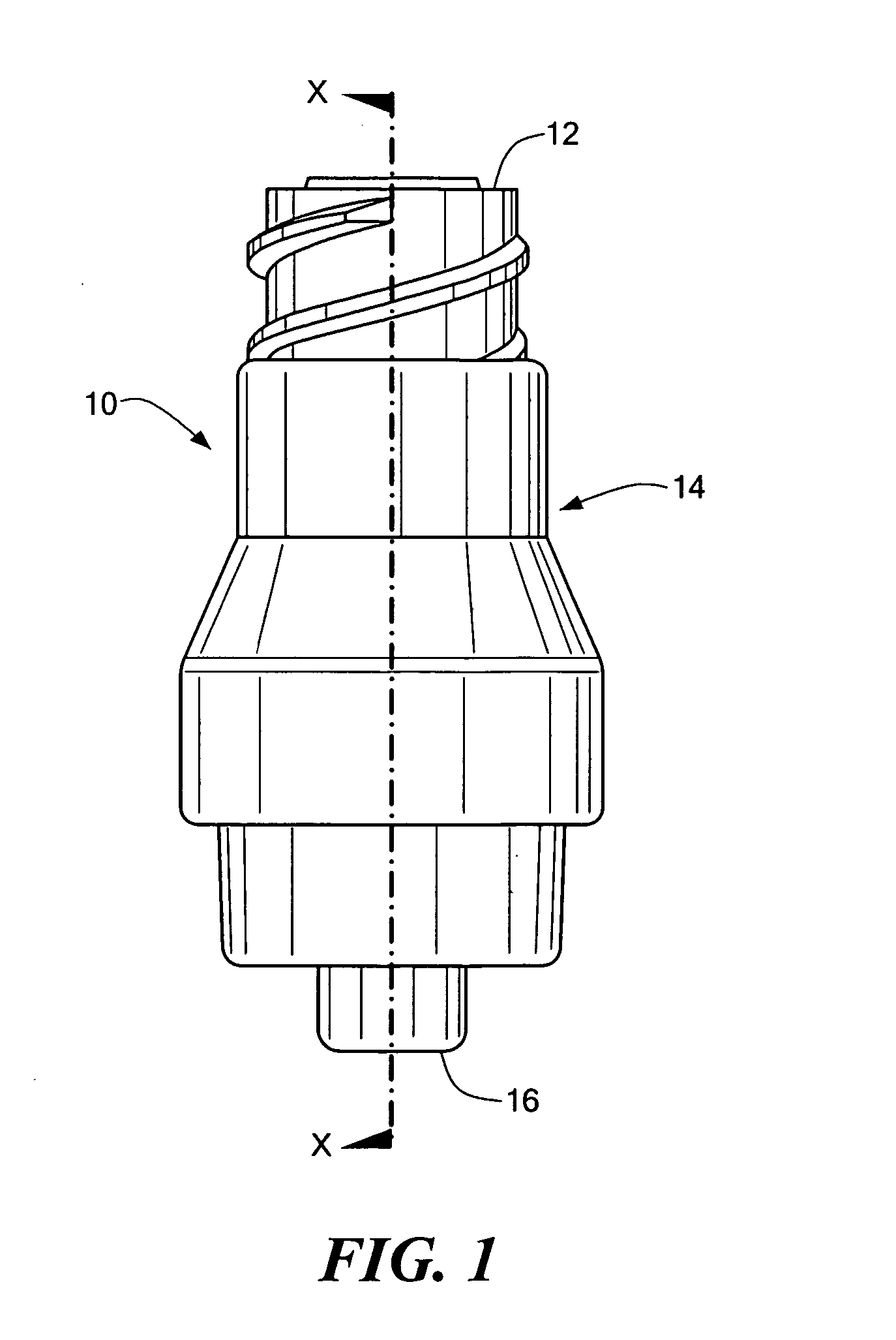
[0044]FIG. 3 schematically shows a cross-sectional view of the medical valve 10 shown in FIG. 1. The housing 18 includes a proximal housing portion 13 that couples with a distal housing portion 15. Among other things, the distal housing portion 15 includes a threaded skirt 40, a post member 20, and a mechanism to couple with the proximal housing portion 13. In the embodiment shown in FIG. 3, a snap fit mechanism is used. As noted above, however, other conventional coupling methods may be used.
[0045] The gland 28 in the embodiment shown in FIG. 3 also has a plurality of thinned sections 52 within a gland portion that fits over the post member 20. The thinned sections 52 facilitate gland stretching over the post member 20 while maintaining a sufficient column strength to force the gland 28 distally.
third embodiment
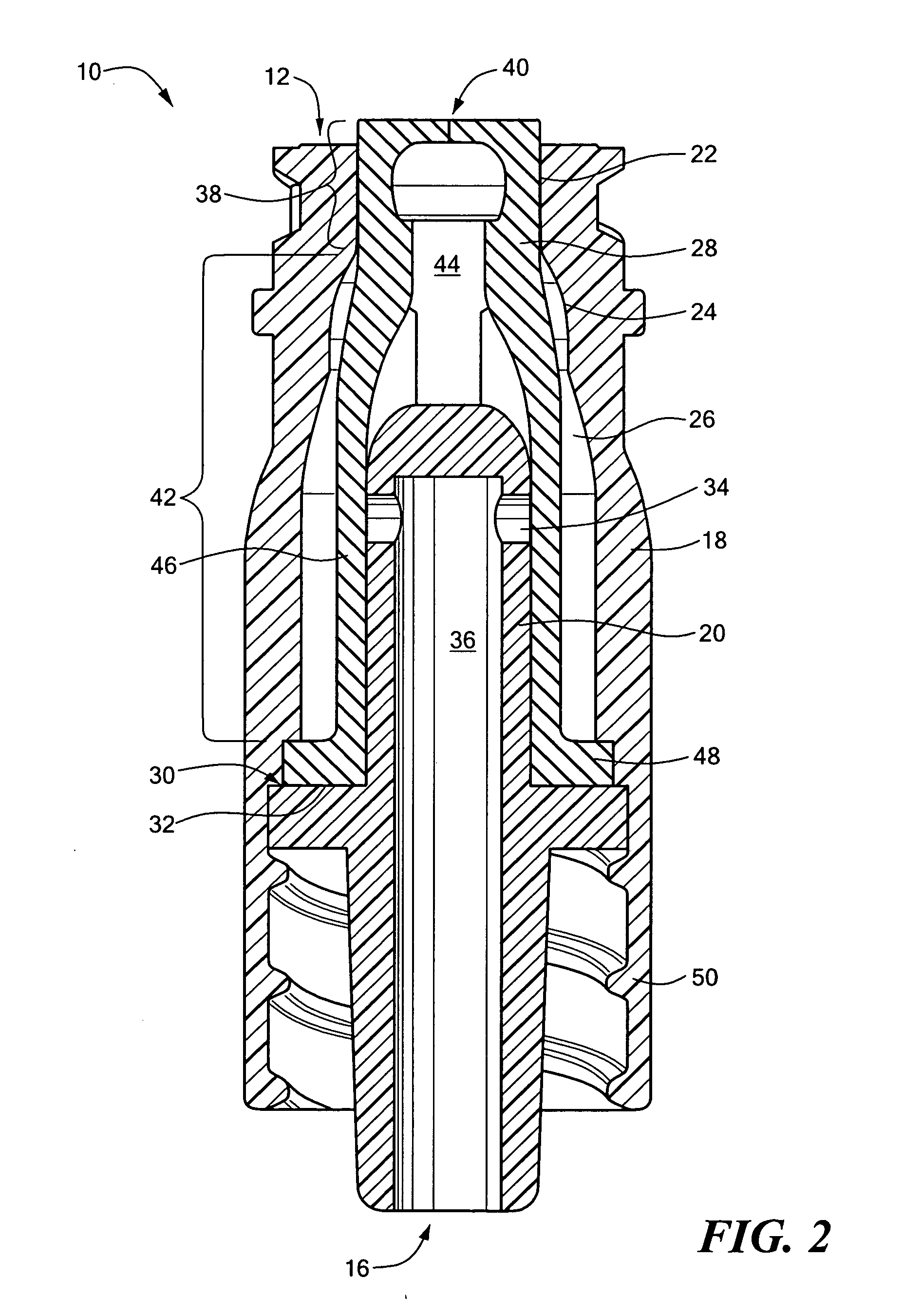
[0046]FIG. 4 schematically shows a cross-sectional view of the medical valve 10 shown in FIG. 1 along line X-X. This embodiment of the valve 10 illustratively is produced from three components; namely, a proximal housing portion 13 having the inlet 12, a distal housing portion 15 having the outlet 16, and a gland 28. The two housing portions 18 and 20, which are formed from a hard plastic material, are snap-fit or welded together to form the valve body / housing 14.
[0047] In a manner similar to other embodiments, the housing portions 18 and 20 form a specially shaped interior. Specifically, the interior has a tapering proximal region 22 to accept a nozzle, a longitudinally adjacent, distally diverging region 24, and a larger central region 26. These regions illustratively are similar to those corresponding regions discussed above with reference to FIG. 2.
[0048] The distal housing portion 15 also has a stationary, hollow post member 20 that terminates at a convex proximal portion. A h...
fourth embodiment
[0064]FIG. 5 schematically shows a cross-sectional view of the medical valve 10 (along line X-X of FIG. 1) in a closed position. More particularly, FIG. 5 schematically shows a cross-sectional view of an embodiment of the medical valve 10 shown in FIG. 1, which also is configured to substantially eliminate fluid drawback during a withdrawal stroke. As noted above, this reduction can result in either a positive pressure at the distal port 16, or a zero net pressure at the distal port 16.
[0065] Among other things, the valve 10 includes a housing 14 containing a resilient, compressible, and stretchable gland 28. More specifically, the housing 18 includes a proximal housing portion 13 coupled with a distal housing portion 15 incorporating a post member 20. Any conventional coupling means may be used, such as ultrasonic welding or conventional snap-fit techniques. The gland 28 and post member 20 cooperate to control fluid flow through the valve 10. In illustrative embodiments, the gland ...
PUM
 Abstract
Description
Claims
Application Information
 - R&D
- Intellectual Property
- Life Sciences
- Materials
- Tech Scout
- Unparalleled Data Quality
- Higher Quality Content
- 60% Fewer Hallucinations
Browse by: Latest US Patents, China's latest patents, Technical Efficacy Thesaurus, Application Domain, Technology Topic, Popular Technical Reports.
© 2025 PatSnap. All rights reserved.Legal|Privacy policy|Modern Slavery Act Transparency Statement|Sitemap|About US| Contact US: help@patsnap.com


