
Desk pad organizer system

a desk pad and organizer technology, applied in the field of desk accessories, can solve the problems of patents that do not recognize the utility none of these patents suggest the concept of joining a desk pad or a supplementary work surface, and the system disclosed in these patents is somewhat limited in utility

Inactive Publication Date: 2005-02-24
MEADWESTVACO CORP
View PDF21 Cites 37 Cited by
  • Summary
  • Abstract
  • Description
  • Claims
  • Application Information

AI Technical Summary

Benefits of technology

[0010] It is a further object of the present invention to provide a desk organizer tray that allows the user to select a particular desk pad to be used with the tray.
[0011] It is yet another object of the present invention to provide a desk pad organizer system that can be manufactured by a process alternative to injection molding or vacuum forming.
[0012] It is yet a further object of the present invention to provide a desk pad organizer system that is easily and cost effectively manufactured.

Problems solved by technology

However, none of these patents suggests the concept of joining a desk pad or supplementary work surface to an organizing system.
Thus, the systems disclosed in these patents are somewhat limited in utility.
However, these patents fail to recognize the utility of joining a desk organizing tray with a desk pad.
Also, the organizing trays in Slater and House are built into the work surface, thus selection of a particular desk pad for use with the trays is impossible.
However, such systems would not be suitable for desktop applications, because they do not present a large enough work surface.
In addition, the calendar is not fixedly connected to the organizing tray, thus each component could be separated and displaced.

Method used


Image

  • Desk pad organizer system
  • Desk pad organizer system
  • Desk pad organizer system

Examples


first embodiment

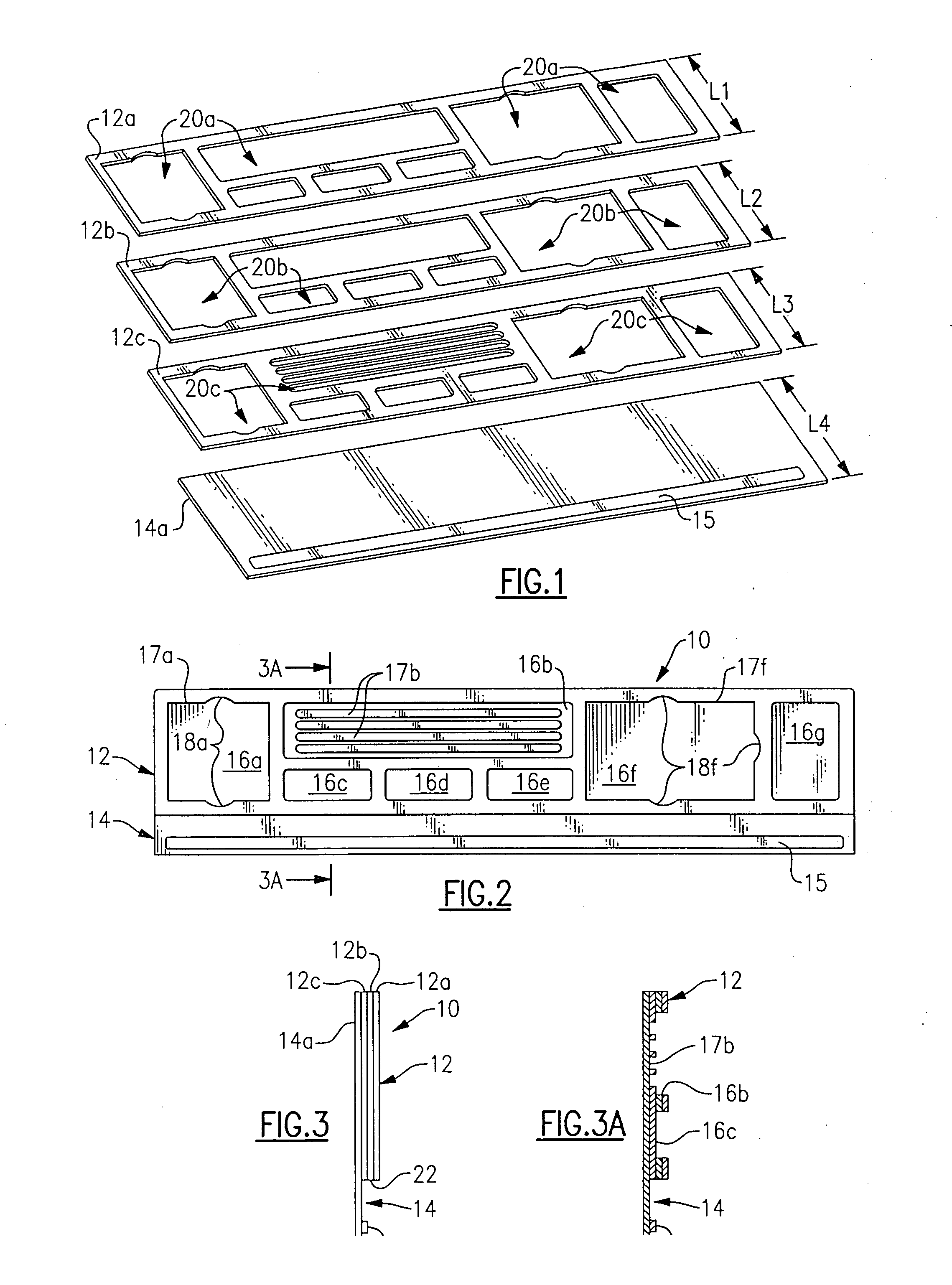
[0024] Referring now to FIGS. 1-3 and 3A, the present invention is shown. A desk organizer tray 10 (FIG. 2) comprises a tray 12, an extension member 14 extending from tray 12, and an attachment element 15 applied to extension member 14. Tray 12 contains several receptacles 16a-16g for holding various desktop items.

[0025] Receptacle 16a is configured and dimensioned to closely receive and hold a pad of adhesive-backed notes (see FIG. 5). The opening to receptacle 16a is defined by a perimeter 17a which contains two opposed finger recesses 18a. Receptacle 16b is configured as a pen and pencil tray, and contains four recesses 17b to cradle pens, pencil or other writing implements (see FIG. 5). Receptacles 16c-16e and 16g are general purpose receptacles for holding such items as push pins, rubber bands, paper clips, coins, and the like (see FIG. 5). Receptacle 16f is configured and dimensioned to closely receive and hold a notepad (see FIG. 5). The opening to receptacle 16f is defined b...

second embodiment

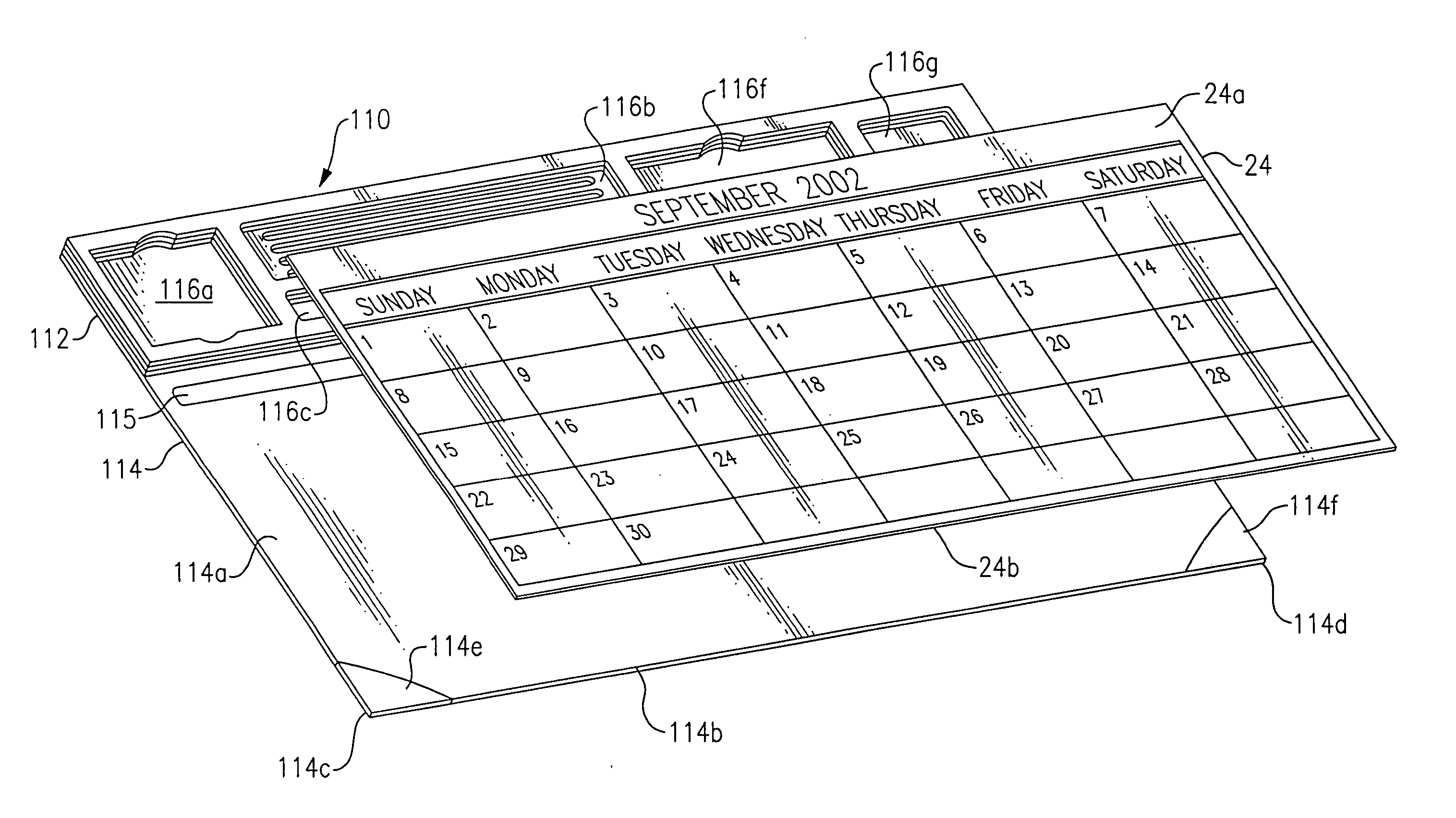
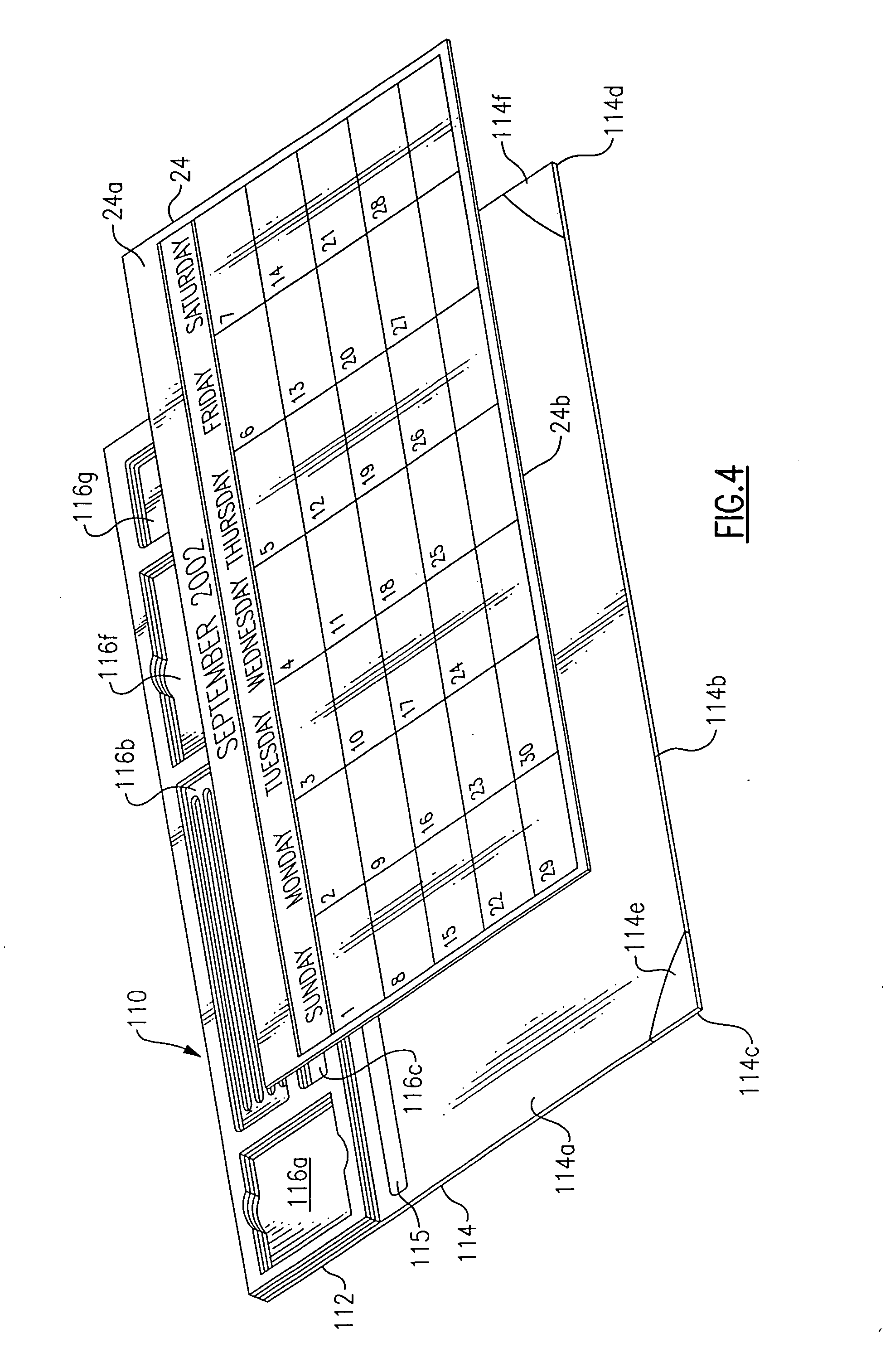
[0026] Attachment element 15 is preferably an adhesive element such as a strip of double-sided tape, glue or a pressure sensitive adhesive substance. As shown, attachment element 15 is preferably applied directly to extension member 14, in the form of a neat band or strip. The purpose of attachment element 15 is to provide a means for attaching a desk pad to extension 14 and for locating the desk pad adjacent to tray 12. This is shown, for a second embodiment, in FIG. 4.

[0027] As best shown in FIG. 1, tray 12 is constructed of three superimposed boards 12a, 12b and 12c. Boards 12a, 12b and 12c contain die-cut hole patterns 20a, 20b and 20c, respectively. As boards 12a-12c are superimposed, hole patterns 20a-20c are in registration with one another to form receptacles 16a-16g. Boards 12a-12c are preferably made of 50 pt black chipboard material or EVA foam material, and they are laminated or glued together to form a single article. The lengths, L1, L2 and L3, of boards 12a-12c are th...


PUM


Abstract

A desk organizer tray, comprising a tray portion, an extension portion extending from the tray portion, and an attachment element applied to the extension portion. The tray portion contains a receptacle for holding desktop items. The tray portion is constructed of a plurality of superimposed board members, each of which contains a hole pattern. The hole patterns of the board members are in registration with one another to form the receptacle. The extension portion includes a board member that extends from the tray portion. The board members of the tray portion are mounted on the board member of the extension portion. The attachment element is applied to the board member of the extension portion. The attachment element serves to attach a desk pad to the extension portion, adjacent to the tray portion.

Description

BACKGROUND OF THE INVENTION [0001] 1. Technical Field [0002] The present invention relates generally desktop accessories, and more particularly to a planning and organizational aid for the desktop. [0003] 2. Background Art [0004] Various items and implements normally associated with working at a desk include pens, pencils, paper clips, notepads, adhesive-backed notes, push pins, rubber bands, and the like. Such items and implements are hereinafter referred to as “desktop items.”[0005] Systems for organizing and holding desktop items have been proposed, as evidenced by the following U.S. patents: U.S. Pat. No. 4,768,298 to Polhemus et al.; U.S. Pat. No. 4,570,793 to O'Neil et al.; and U.S. Pat. No. 4,176,743 to Fitzpatrick. These patents disclose modular and reconfigurable organizing systems. The patents to Polhemus and Fitzpatrick also disclose the use of day calendars in conjunction with such systems. However, none of these patents suggests the concept of joining a desk pad or supp...

Claims


Application Information

Patent Timeline
IPC IPC(8): A47B13/00A47B97/00B42D5/00B43L3/00B43M99/00B65D1/34
CPCB42D5/005B43L3/00B43M99/009B43M99/008B43M99/001
Inventor ADAMS, DUANE D.
Owner MEADWESTVACO CORP
Learn More