
Bandwidth Limited Sampling Circuit of High Linearity

a sampling circuit and high linearity technology, applied in the field of electrical/electronic circuit design, can solve the problems of non-linear response in terms of the overall sampling operation, undesirable non-linearity,

Active Publication Date: 2005-03-03
TEXAS INSTR INC
View PDF6 Cites 5 Cited by
  • Summary
  • Abstract
  • Description
  • Claims
  • Application Information

AI Technical Summary

Problems solved by technology

One problem with such an approach is that some of the components performing such removal may have non_linear characteristics, which results in a non_linear response in terms of the overall sampling operation.
The non_linearity is undesirable in several environments.

Method used


Image

  • Bandwidth Limited Sampling Circuit of High Linearity
  • Bandwidth Limited Sampling Circuit of High Linearity
  • Bandwidth Limited Sampling Circuit of High Linearity

Examples


Embodiment Construction

[0016] 1. Overview

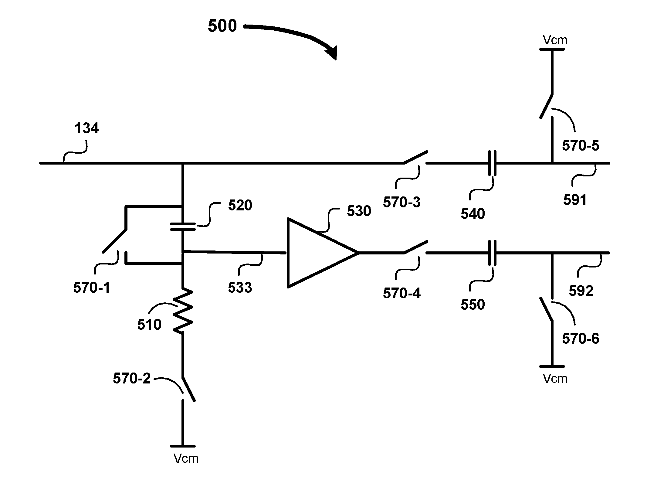
[0017] A sampling circuit implemented according to one aspect of the present invention contains a first circuit portion which limits the bandwidth of an input signal containing both source signal and a noise signal, and a second circuit portion samples the bandwidth limited signal. Noise signal, which is generally of high frequency, is substantially absent at an output of the sampling circuit due to the operation of the first circuit portion. As a result, the immunity of the output signal generated by the sampling circuit to noise is enhanced. In one embodiment described below, the first circuit portion is implemented as a R_C circuit operating as a low pass filter, and the second circuit portion is implemented using a switched capacitor.

[0018] According to another aspect of the present invention, the sampling circuit is implemented using two paths, with the first circuit path sampling the input signal (including source signal and noise signal) and the second cir...


PUM


Abstract

A bandwidth limited sampling circuit of high linearity may be implemented by using a first circuit portion to limit the bandwidth of the input signals, and using a second circuit portion to sample the bandwidth limited input signal. The first circuit portion and the second circuit portion may be implemented using separate components. In an alternative embodiment, bandwidth limiting is implemented by taking a difference of a sampled input signal from a sampled high frequency components of the input signal.

Description

CROSS REFERENCE TO RELATED APPLICATIONS [0001] The present application is related to and claims priority from co_pending U.S. provisional patent application entitled, “Noise Suppression Scheme for Sampling Circuit”, Filed on: Aug. 29, 2003, Ser. No. 60 / 498,801, Attorney Docket Number: TI-919PS, naming as inventors: AYYAGARI et al, and is incorporated in its entirety herewith into the present application.BACKGROUND OF INVENTION [0002] 1. Field of the Invention [0003] The present invention relates to the design of electrical / electronic circuits, and more specifically to a method and apparatus for attaining a bandwidth limited sampling circuit of high linearity. [0004] 2. Related Art [0005] A sampling circuit generally refers to a component which samples a signal level of an input signal (e.g., analog signal) at a particular instant of time and provides an output signal having the signal level to other components for a long duration. In general, a sampling circuit samples an input anal...

Claims


Application Information

Patent Timeline
IPC IPC(8): G11C27/02H04N5/357H04N5/372H04N5/378
CPCH04N5/378G11C27/026H04N25/78H04N25/75
Inventor AYYAGARI, RAVISHANKAR S.PENTAKOTA, VISVESVARAYA A.
Owner TEXAS INSTR INC
Learn More