

Image photographing apparatus and image processing method
a technology of image processing and image processing, which is applied in the field of image processing apparatus and image processing method, can solve the problems of low image quality of a generated image, and it is not easy to set the view point position of a reconstructed image in an actual space, and achieves the effect of easy designation of an arbitrary position
- Summary
- Abstract
- Description
- Claims
- Application Information
AI Technical Summary
Benefits of technology
Problems solved by technology
Method used
Image

Examples
first embodiment
(First Embodiment)
In the following, a photographing apparatus constituting a first embodiment of the present invention will be explained in detail, with reference to accompanying drawings.
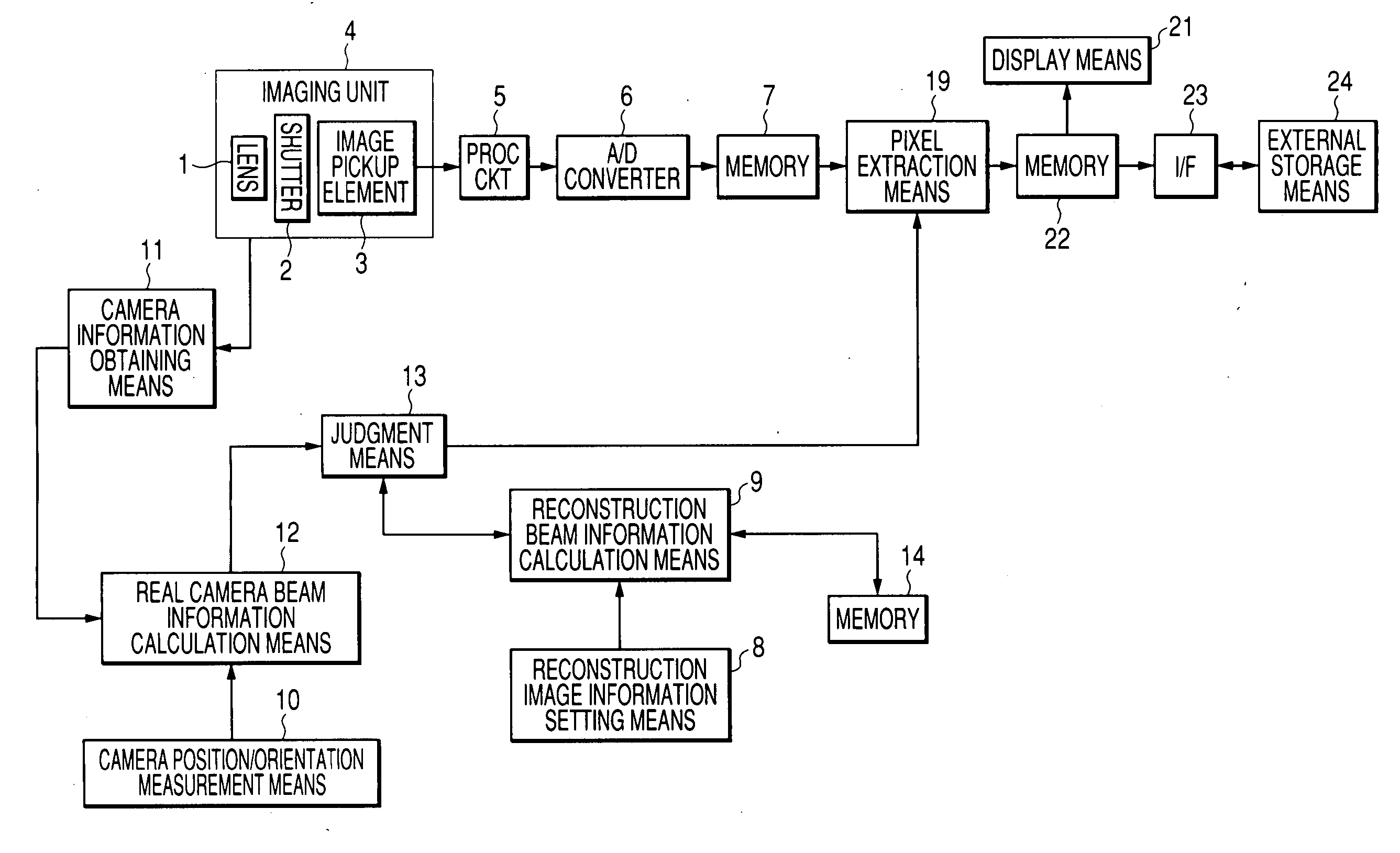
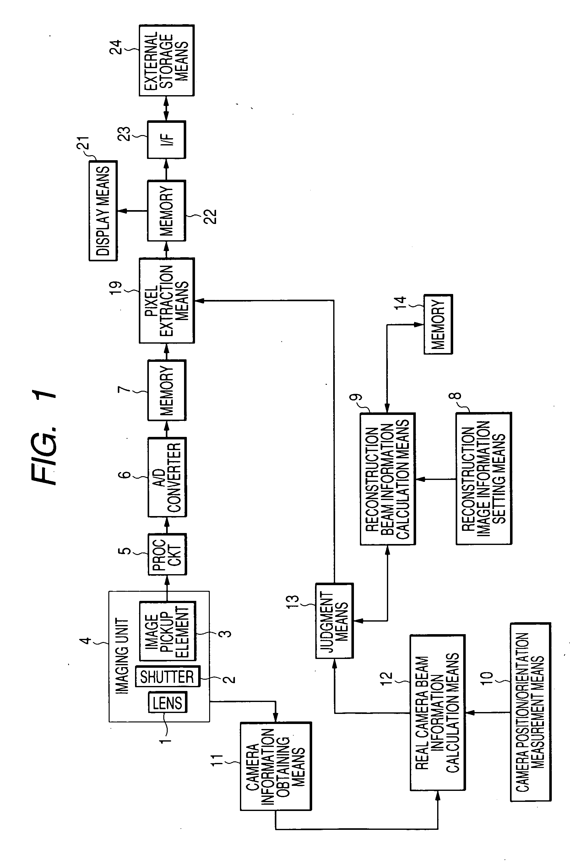
FIG. 1 is a block diagram of a photographing apparatus of the first embodiment.
Referring to FIG. 1, there are shown a photographing lens 1; a shutter 2 provided with a diaphragm function; an image pickup element 3 for converting an optical image into an electrical signal for example by a CCD; a part of an imaging unit 4 including a lens, a diaphragm, an image pickup element etc.; a process circuit 5 for executing a known camera signal process such as a gamma correction; an A / D converter 6 for converting an analog output of the process circuit 5 into a digital signal; a memory 7 for storing image data outputted from the A / D converter 6; reconstruction image information setting means 8 for setting information of a reconstruction image; reconstruction beam information calculation means 9 for calcu...
second embodiment
(Second Embodiment)
FIG. 10 is a block diagram in case the image pickup unit 3 is changed from CCD type to a CMOS sensor 27. In the present and ensuing embodiments, blocks represented by a same number are assumed to have a same function unless specified otherwise and will not be explained in repetition.
Since a CMOS sensor can output a pixel value independently for each pixel, it is rendered possible to output an address for directly specifying a pixel from the pixel extraction means 19 to the CMOS sensor thereby receiving a corresponding pixel value, and to store it in the memory 22 through the process 5 and the A / D conversion 6.
Such use of the CMOS sensor in the image pickup portion allows to dispense with a memory for temporarily storing the photographed image, thereby providing an advantage of reducing the dimension and the cost of the hardware. However the CMOS sensor is merely an example, and it is naturally possible to utilize another sensor capable of data output in the un...
third embodiment
(Third Embodiment)
As the first and second embodiments are not provided with display means for displaying a reconstruction image, it is not possible, when the image reconstruction is started, to recognize the current status of image reconstruction or when the image reconstruction will be completed. Therefore, the present embodiment is provided with monitor means 28 as shown in FIG. 11, for displaying an image under photographing and an image under reconstruction, according to a switching by the user. It is naturally possible also to provide the second embodiment with similar monitor means.
FIG. 12 is a block diagram of the monitor means 28, wherein shown are switching control means 20 for switching information stored in the memory 7 and the memory 22, and display means 21 for visibly displaying information from the switching control means 20.
In the foregoing, a live image under photographing and an image under reconstruction are rendered switchable, but it is also possible to disp...
PUM
 Abstract
Description
Claims
Application Information