Capsule endoscope

a technology of endoscope and capsule, which is applied in the field of capsule endoscope, can solve the problems of difficult control of the direction of the objective optical system, the inability to capture images inside the body cavity, and the inability to use such an omnidirectional lateral view optical system, and achieve the effect of satisfactorily illuminating the entire image pickup rang

Inactive Publication Date: 2005-03-03
HOYA CORP
View PDF35 Cites 188 Cited by
  • Summary
  • Abstract
  • Description
  • Claims
  • Application Information

AI Technical Summary

Benefits of technology

[0010] The present invention is advantageous in that it provides a capsule endoscope configured to have an omnidirectional lateral view optical system allowing observation of all directions as an objective optical system and to be capable of illuminating all the image pickup range satisfactorily.

Problems solved by technology

However, with such a capsule endoscope 100 being introduced into a body cavity, it is very difficult to control the direction of the objective optical system 101 (that is, to control the attitude of the capsule endoscope 100).
However, even though the aforementioned omnidirectional lateral view optical system is originally designed to be applicable to indoor shooting, capturing images inside a body cavity (with almost no light reaching the object in comparison with indoor shooting with a certain amount of light) by use of such an omnidirectional lateral view optical system is almost impossible.

Method used


Image

  • Capsule endoscope
  • Capsule endoscope
  • Capsule endoscope

Examples


first embodiment

[0047] First Embodiment

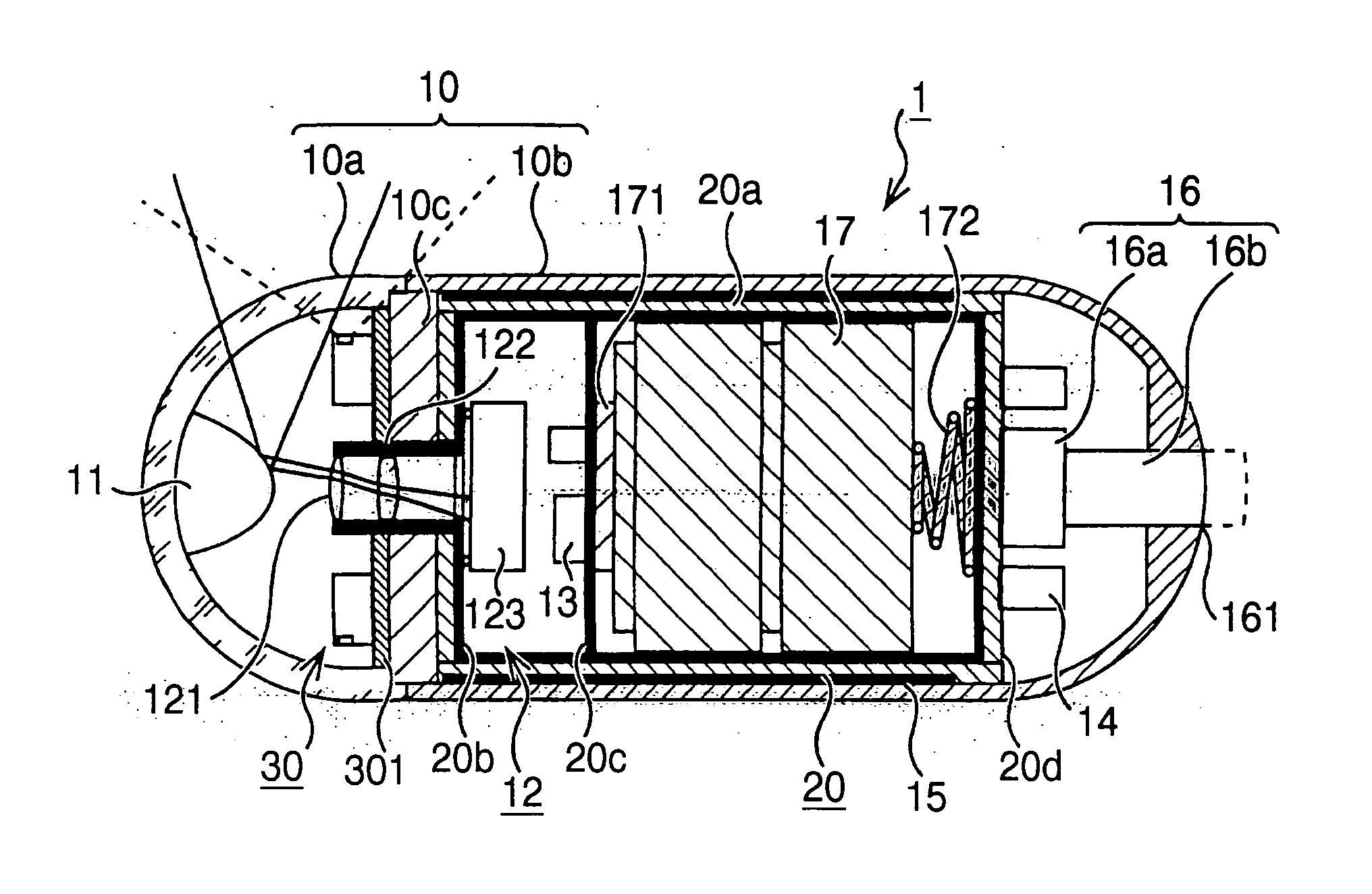
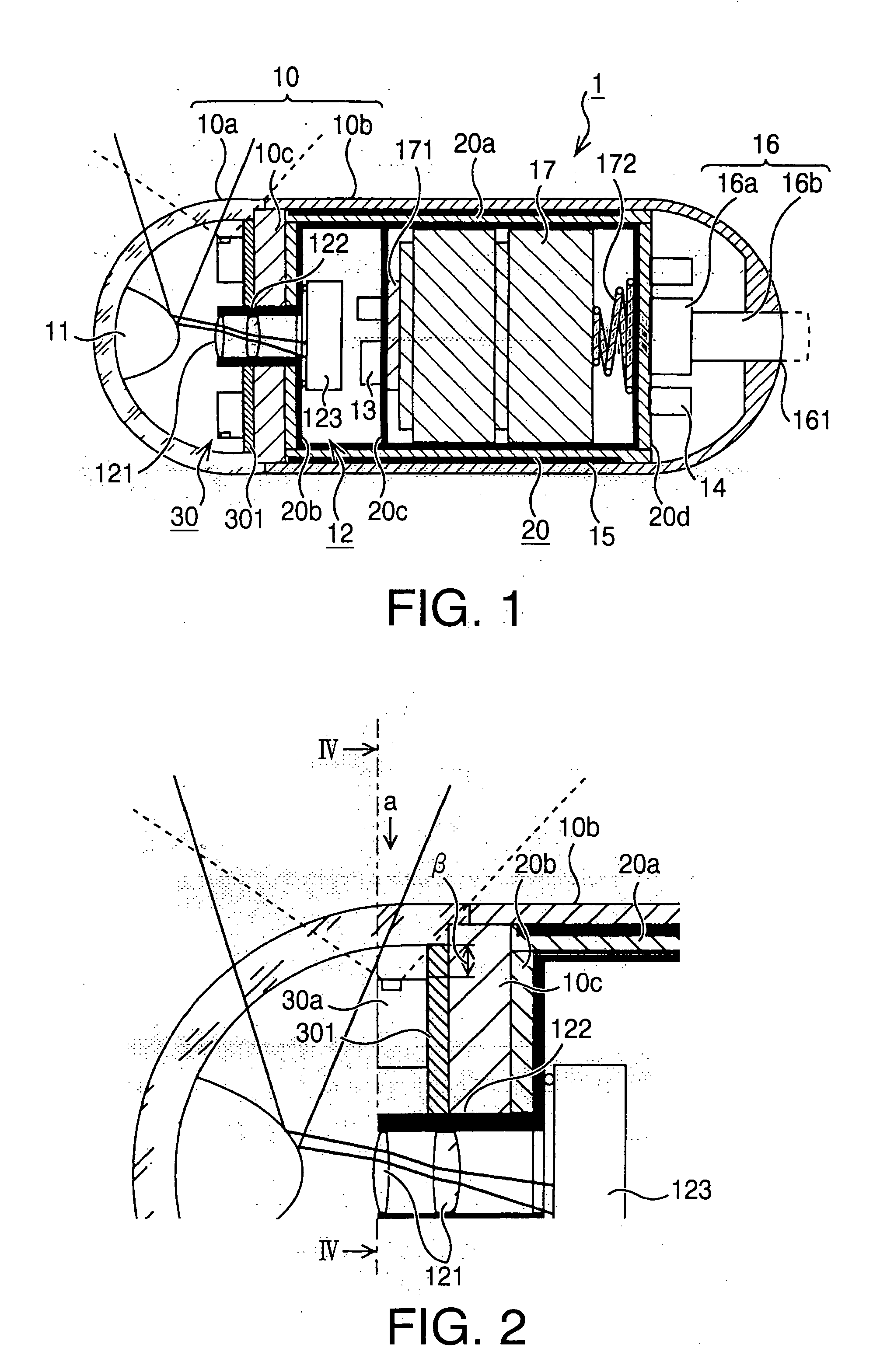
[0048]FIG. 1 is a schematic diagram showing the internal composition of a capsule endoscope 1 in accordance with a first embodiment of the present invention. For the sake of clear and easy understanding of the explanation, part of the capsule endoscope 1 drawn on the left-hand side of FIG. 1 will be called “the front” and part of the capsule endoscope 1 drawn on the right-hand side of FIG. 1 will be called “the rear”.

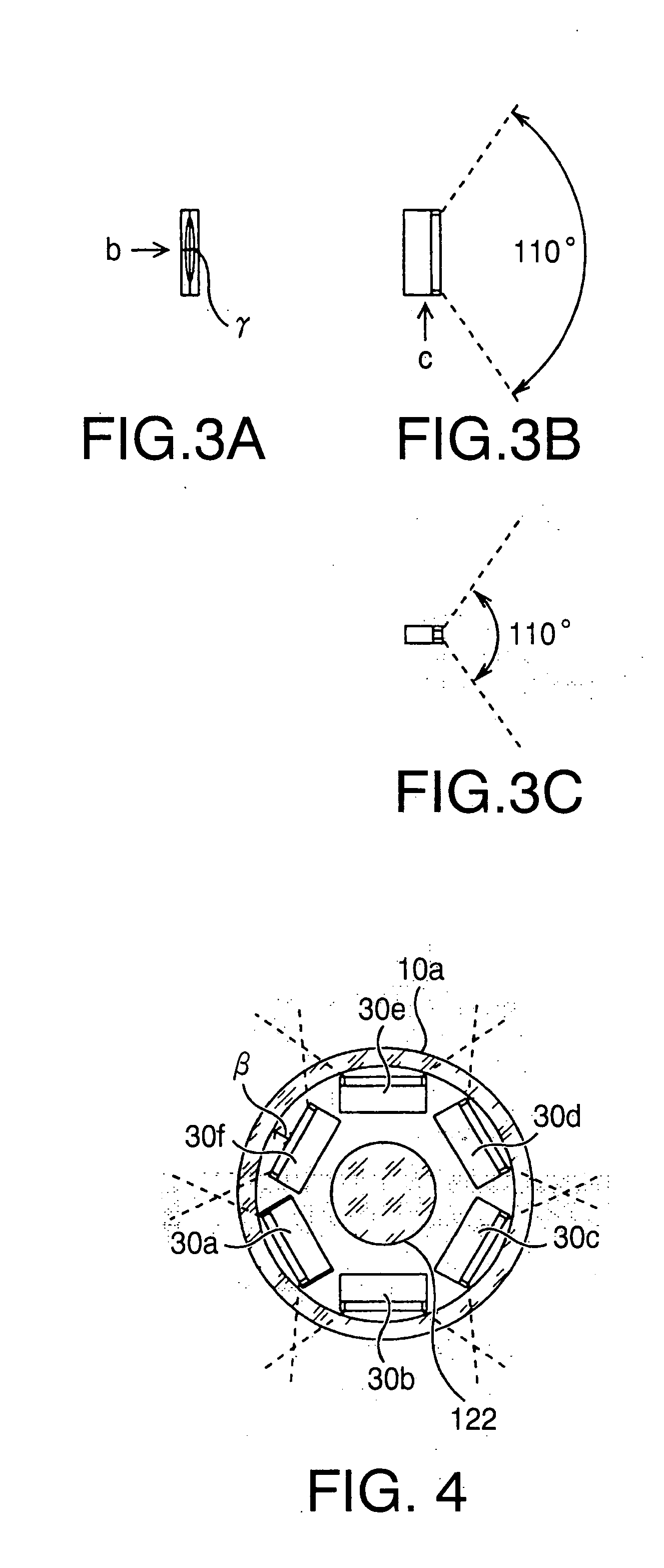
[0049] As shown in FIG. 1, the capsule endoscope 1 includes a convex reflecting mirror 11, an image pickup device 12, an image processing circuit 13, a transmission circuit 14, a transmission antenna 15, a lighting unit 30, a battery 17 supplying electric power to each component, an internal case 20 storing the battery 17 and electrically connecting circuit components (explained later) mounted thereon, a power switch 16, and a casing 10 storing and protecting the above components.

[0050] The casing 10 includes a cylindrical body10b having a hemis...

second embodiment

[0066] Second Embodiment

[0067]FIG. 5 is a schematic diagram showing the internal composition of a capsule endoscope 1B in accordance with a second embodiment of the present invention. FIG. 6 is a schematic diagram enlarging part of the capsule endoscope 1B around two LEDs 30a and 40a of the lighting unit 30. In FIGS. 5 and 6, the same reference numerals as those of the first embodiment designate the same components as those of the first embodiment and thus repeated description thereof is omitted for brevity.

[0068] A transparent cover 10aa is formed of a transparent and acid resistant material in a substantially cylindrical shape to have a hemispheric front end. The internal surface of the transparent cover 10aa is coated with a transparent electrically conductive material (transparent conductive layer 110) such as ITO (Indium Tin Oxide). The transparent conductive layer 110 is formed into a circuit pattern by photo-lithography, etching, etc., and a positive wire and negative wire o...


PUM


Abstract

A capsule endoscope, including an omnidirectional lateral view optical system allowing observation of all directions as the objective optical system and also being capable of illuminating all the image pickup range satisfactorily, is provided. On a positioning plate inside the capsule, six LEDs are arranged at even angular intervals (60 degrees) with their light emitting surfaces facing a transparent cover of the capsule. The light emitting surface of each LED is placed at a position that is a prescribed distance β inwardly apart from the interior surface of the transparent cover of the capsule.

Description

BACKGROUND OF THE INVENTION [0001] The present invention relates to a capsule endoscope which is introduced into a body cavity of a patient for picking up images of the inside of the body cavity. [0002] In recent years, a capsule endoscope system, including a capsule endoscope (an endoscope in the shape of a small capsule) which is swallowed by a patient to be introduced into the patient's body cavity for picking up images of the inside of the body cavity and a processor and a monitor which are placed outside the patient's body, is being developed in order to eliminate the pain of patients in orally introducing (swallowing) the tip of a conventional electronic endoscope formed as a flexible tube. [0003] The capsule endoscope swallowed (orally introduced into a body cavity) by the patient picks up an image of the inside of the body cavity, converts the image into an image signal, and wirelessly transmits the image signal to the processor placed outside the patient's body. The process...

Claims


Application Information

Patent Timeline
Patent Type & Authority Applications(United States)
IPC IPC(8): A61B1/00G02B23/24A61B1/05A61B1/273A61B1/31A61B5/07
CPCA61B1/00016A61B1/00096A61B1/041A61B1/0684A61B1/00181A61B1/31A61B5/073A61B1/00177A61B1/2733A61B1/0605
Inventor KANAZAWA, MASAFUMI
Owner HOYA CORP
Why Eureka
Try Eureka