Knee balancing block

a balancing block and knee technology, applied in the field of orthopaedic surgical devices, can solve the problems of increasing the time and difficulty of surgery in arastically

Active Publication Date: 2005-03-03
ORTHO DEV CORP
View PDF45 Cites 234 Cited by
  • Summary
  • Abstract
  • Description
  • Claims
  • Application Information

AI Technical Summary

Benefits of technology

[0015] The prior art is thus characterized by several disadvantages that are addressed by the present invention. The present invention minimizes, and in some aspects eliminates, the above-mentioned failures, and other problems, by utilizing the methods and structural features described herein.

Problems solved by technology

The surgeon must then remove at least one of the pins from the distal femur, and re-secure the at least one pin to the bone for another attempt at securing the knee balancing device to the bone in an aligned position, which drastically increases the time and difficulty of the surgery.
The prior art knee balancing devices may also lead to over resection of the bones in the knee joint, as substantially equivalent rectangular gaps are sought, which may potentially cause problems if a later revision surgery becomes necessary.
This device is characterized by several disadvantages, including the need to connect a complex series of brackets to a base creating a scaffolding to which several devices may be removably attached.
This device is disadvantageous because there is no mechanism for adjusting the rotation of the A / P cutting guide, making each step in the surgery crucial, leaving little to no room for human error.

Method used


Image

  • Knee balancing block
  • Knee balancing block
  • Knee balancing block

Examples


Embodiment Construction

[0040] For the purposes of promoting an understanding of the principles in accordance with the invention, reference will now be made to the embodiments illustrated in the drawings and specific language will be used to describe the same. It will nevertheless be understood that no limitation of the scope of the invention is thereby intended. Any alterations and further modifications of the inventive features illustrated herein, and any additional applications of the principles of the invention as illustrated herein, which would normally occur to one skilled in the relevant art and having possession of this disclosure, are to be considered within the scope of the invention claimed.

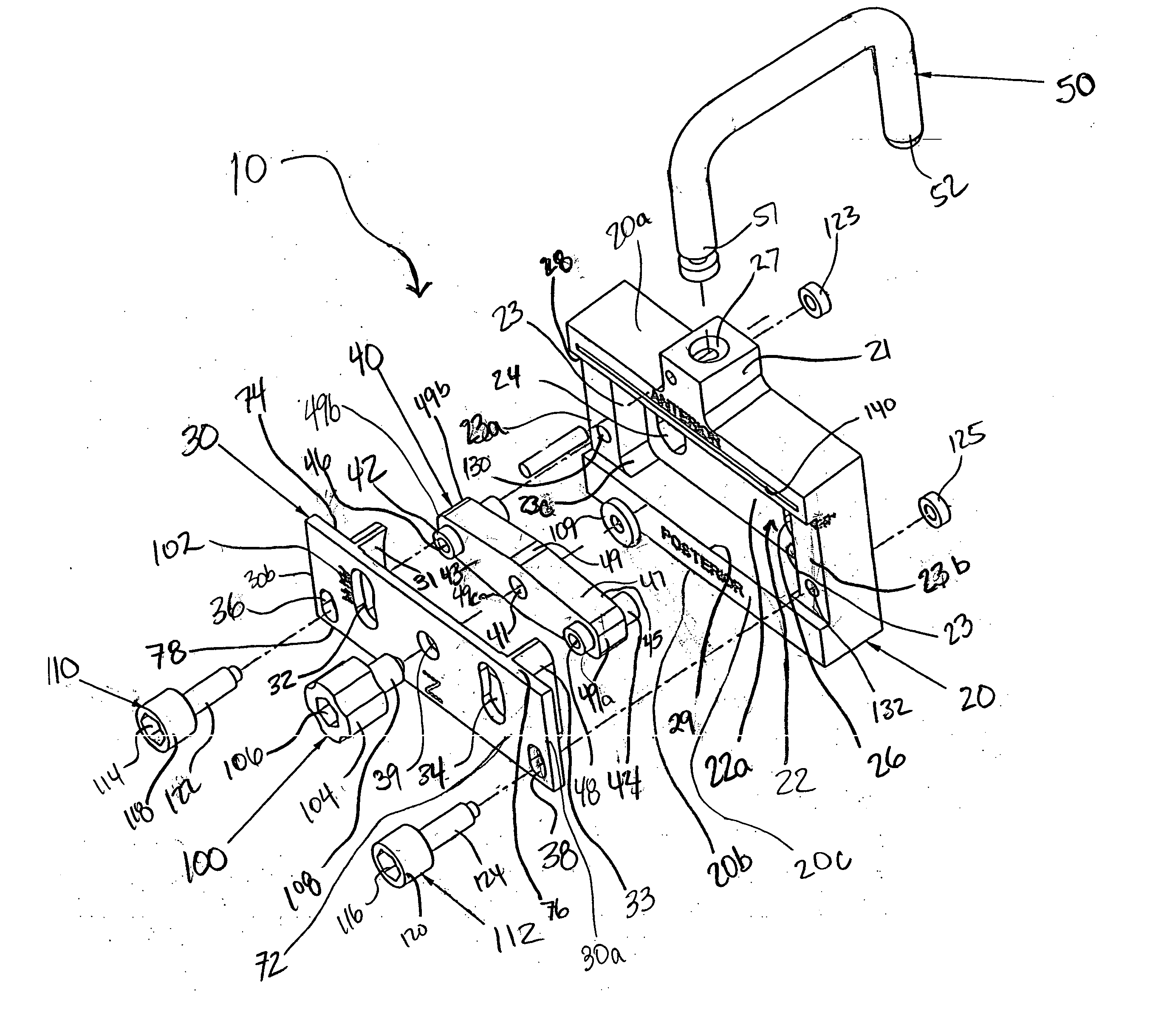
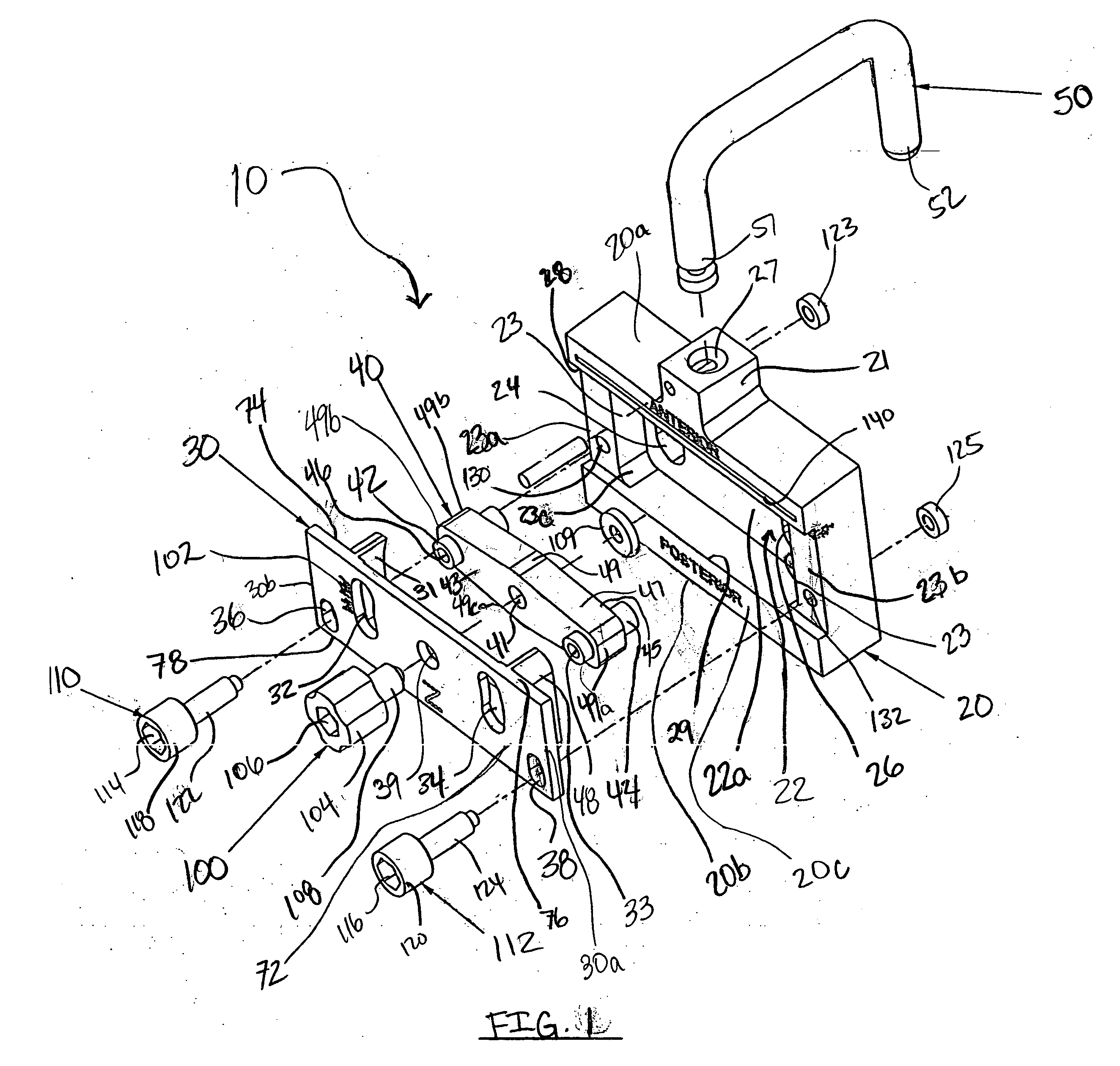
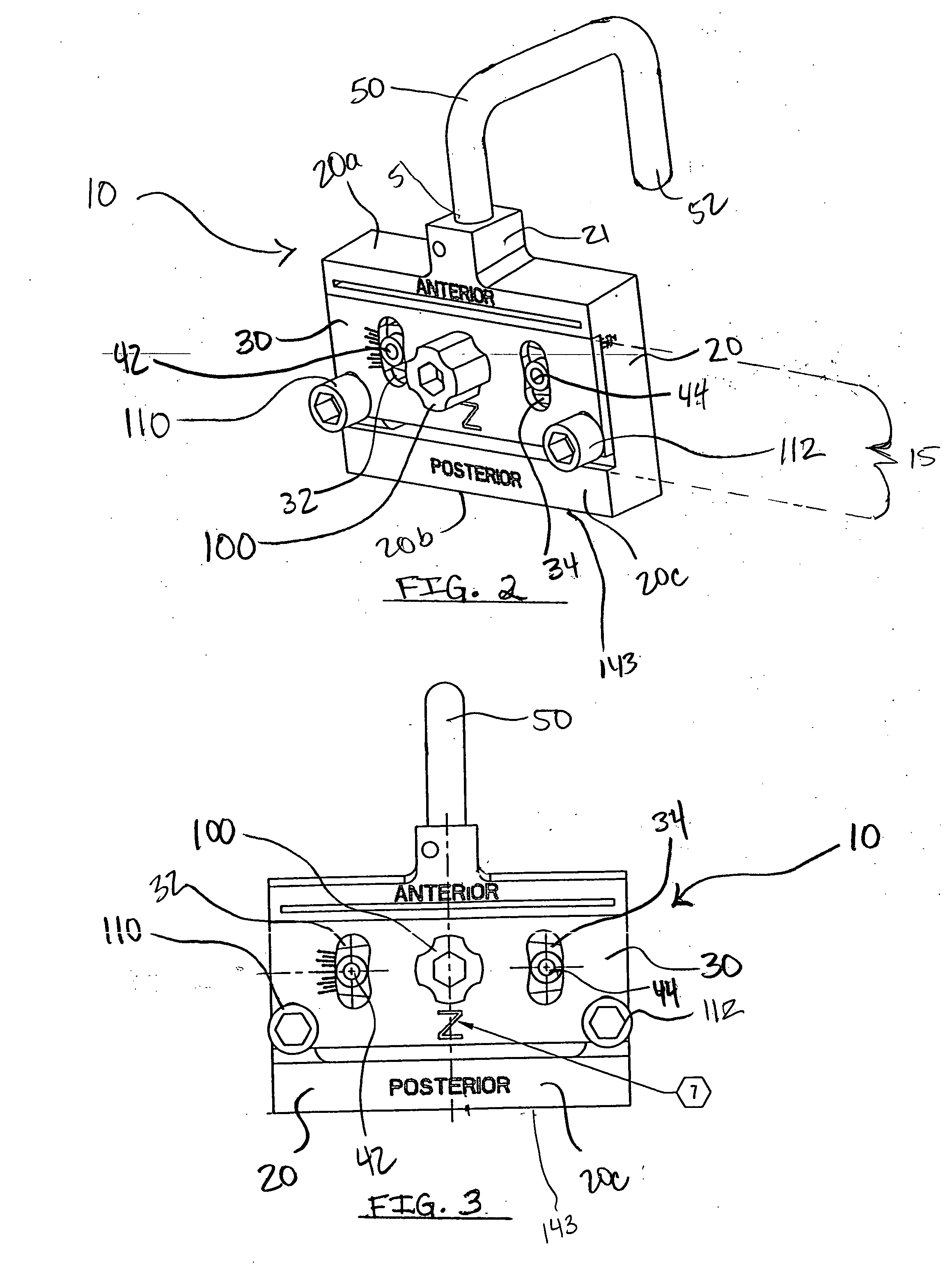
[0041] Applicants have discovered that a total knee arthroplasty (TKA) is greatly enhanced by utilizing a unique A / P cutting guide device 10 that may be moved in both a rotational and translational manner with respect to a distal end of a femur after the A / P cutting guide device 10 has been secured, or pinne...


PUM


Abstract

An orthopedic A/P cutting guide device, including a cut guide member, a support member and a positioning member for permitting both (i) rotational, and (ii) translational movement after the A/P cutting guide device has been attached to the distal femur by quick pins or other securing devices, is disclosed. Rotational movement may occur by loosening a knob thereby releasing the positioning member and the cut guide member from the support member, which may be fixed in position by the quick pins, and rotating the positioning member and the cut guide member together. Translational movement may occur by loosening a plurality of knobs thereby releasing the cut guide member from the support member and the positioning member, and moving the cut guide member anteriorly or posteriorly. After the device has been rotated and translated, the knobs may be tightened, thus securing the device from further movement.

Description

CROSS-REFERENCE TO RELATED APPLICATIONS [0001] This application claims the benefit of U.S. Provisional Application No. 60 / 398,289, filed Jul. 23, 2002, and U.S. Provisional Application No. 60 / 474,454 filed May 30, 2003, which are hereby incorporated by reference herein in their entireties, including but not limited to those portions that specifically appear hereinafter, the incorporation by reference being made with the following exception: In the event that any portion of either of the above-referenced applications is inconsistent with this application, this application supercedes said portion of said above-referenced applications.STATEMENT REGARDING FEDERALLY SPONSORED RESEARCH OR DEVELOPMENT [0002] Not Applicable. BACKGROUND OF THE INVENTION [0003] 1. The Field of the Invention [0004] The present invention relates generally to orthopedic surgical devices, and more particularly, but not necessarily entirely, to a device and method for balancing flexion and extension gaps in total ...

Claims


Application Information

Patent Timeline
Patent Type & Authority Applications(United States)
IPC IPC(8): A61B17/15A61B17/58A61FA61F5/00
CPCA61B17/157A61B17/155
Inventor CALTON, THOMAS F.LOWE, MATTHEW M.ENSIGN, MICHAEL D.SHAVER, SCOTT
Owner ORTHO DEV CORP
Why Eureka
Try Eureka