Method to snapshot and playback raw data in an ultrasonic meter

a raw data and ultrasonic meter technology, applied in the direction of volume metering, instruments, nuclear elements, etc., can solve the problems of measurement device imperfection, measurement device errors, and difficulty in diagnosing problems in the field of measurement device problems,

Active Publication Date: 2005-03-10
MICRO MOTION INC
View PDF2 Cites 11 Cited by
  • Summary
  • Abstract
  • Description
  • Claims
  • Application Information

AI Technical Summary

Benefits of technology

Thus, the present invention comprises a combination of features and advantages which enable it to overcome various problems of prior devices. The various characteristics described above, as sell as other features, will be readily apparent to those skilled in the art upon reading the following detailed description of the preferred embodiments of the invention, and by referring to the accompanying drawings.

Problems solved by technology

Measurement devices are not perfect, however.
They are known to make errors in measurements, there being many reasons why measurement devices may not measure a characteristic-of-interest accurately.
Furthermore, diagnosing problems with measurement devices in the field can be a difficult and troublesome experience.
The problem is exacerbated when input data varies considerably from one field location to another, resulting in no single or small data set being representative for typical conditions in the field.
Unfortunately, measurement errors occur.
In the case of an ultrasonic meter, one or more of the measurements may deviate so significantly from a benchmark that it indicates a problem either with the fluid flow or with the meter itself.
Typically, it will be difficult to diagnose the problem based on only the velocity and speed of sound measurements.
Similarly, it may be difficult to determine based only on velocity and speed of sound measurements whether there exists a measurement error or whether an unusual or notable event is occurring in the medium being measured by the measurement device.
One problem with such an approach, however, is its failure to collect data in between the temporal measurement points.
As a result, a substantial amount of data is not collected.
If a cause or condition of a meter problem takes place while data is not being recorded, detection of the cause or condition can be missed.
A problem with this approach, however, is that it does not collect data prior to the trigger event.
This is a problem when the trigger event is only a culmination of a trend or ongoing problem in existence before the trigger event.
In such a case, it may be difficult to identify the problem by use of an in-circuit simulator.
A drawback with both of these approaches is that they rely greatly on the knowledge and training of the technical persons who are sent to investigate the problem at the meter location.
There is little opportunity to carefully diagnose the problem elsewhere because much of the analysis and effort to rectify a problem takes place at the meter location.
Both of these approaches record only limited data, either at the time of an event or at spaced intervals.
This is a problem because a more complete set of data is important when attempting to identify a problem with the measurement device.
A problem with the measurement of fluid flow may correlate to any one of a number of different issues.
A peak selection error may be due to noise, turbulence in the fluid flow, or incorrect default values in the meter's software.
However, because of the high amount of data that is processed or refined down in a high input-low output processing scheme, crucial information may go unreported or underreported, leading to an inability to adequately describe fleeting anomalous conditions.
If these fleeting conditions are not captured by the method used to identify a problem with the measurement device, they go undetected.

Method used


Image

  • Method to snapshot and playback raw data in an ultrasonic meter
  • Method to snapshot and playback raw data in an ultrasonic meter
  • Method to snapshot and playback raw data in an ultrasonic meter

Examples


Embodiment Construction

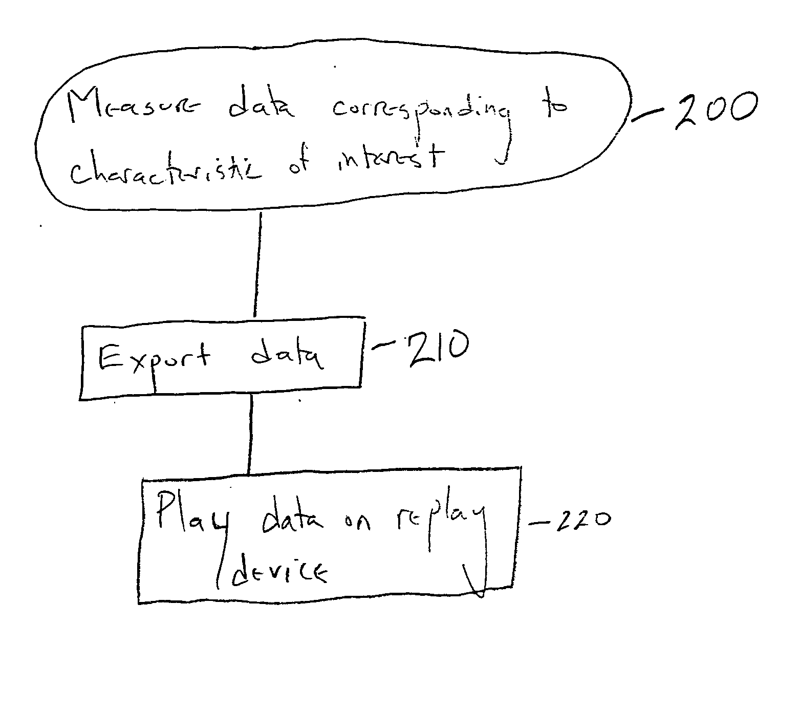
The novel solution of the invention is a system and method to take a “snapshot” of meter performance. This includes: 1) recording a continuous stream of raw data into a format suitable for transport to a site better suited for debug and diagnosis; and 2) replaying the data on a replay device such that time, as seen by the system, may be “frozen” at will and any instant of the stream examined.

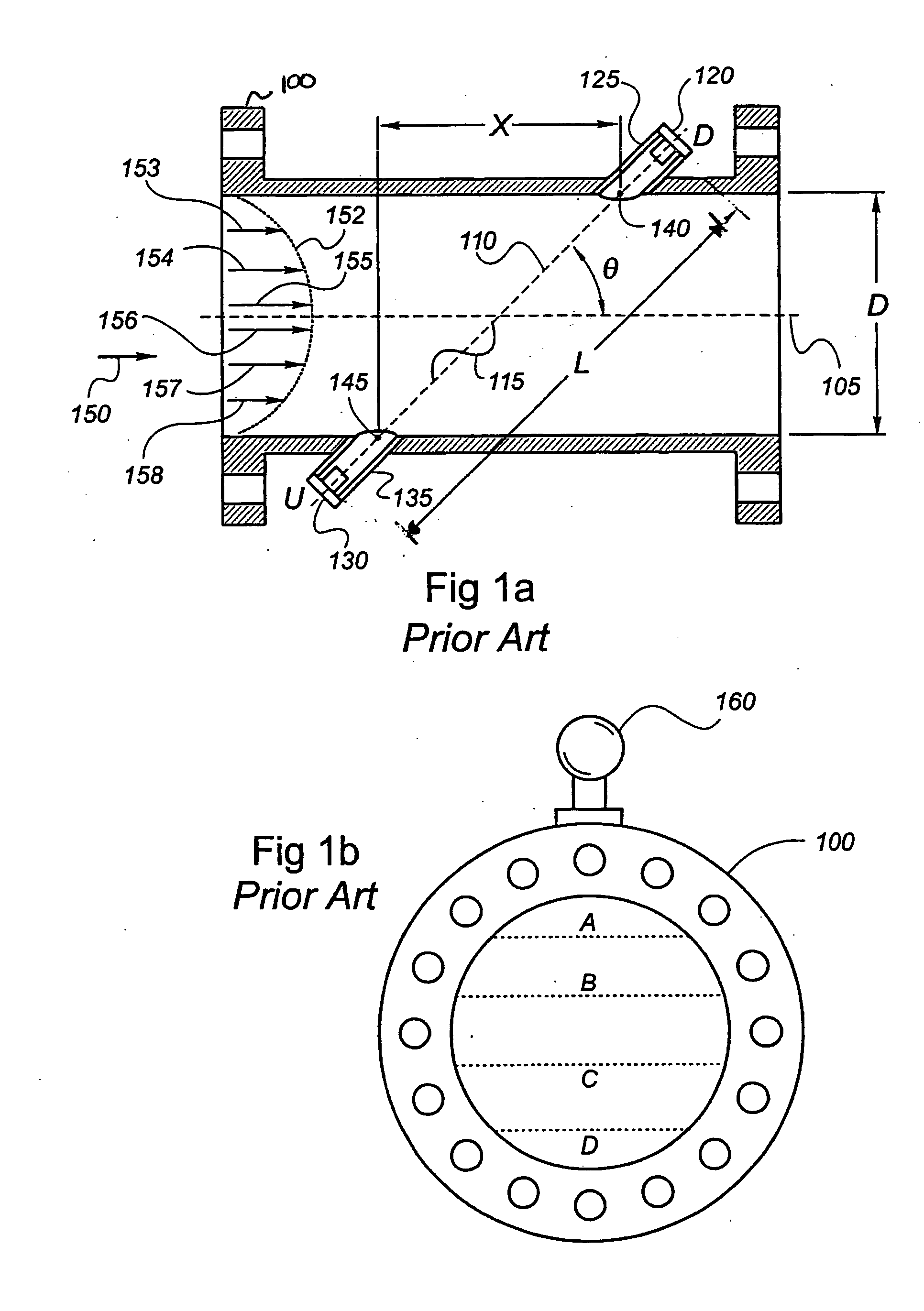
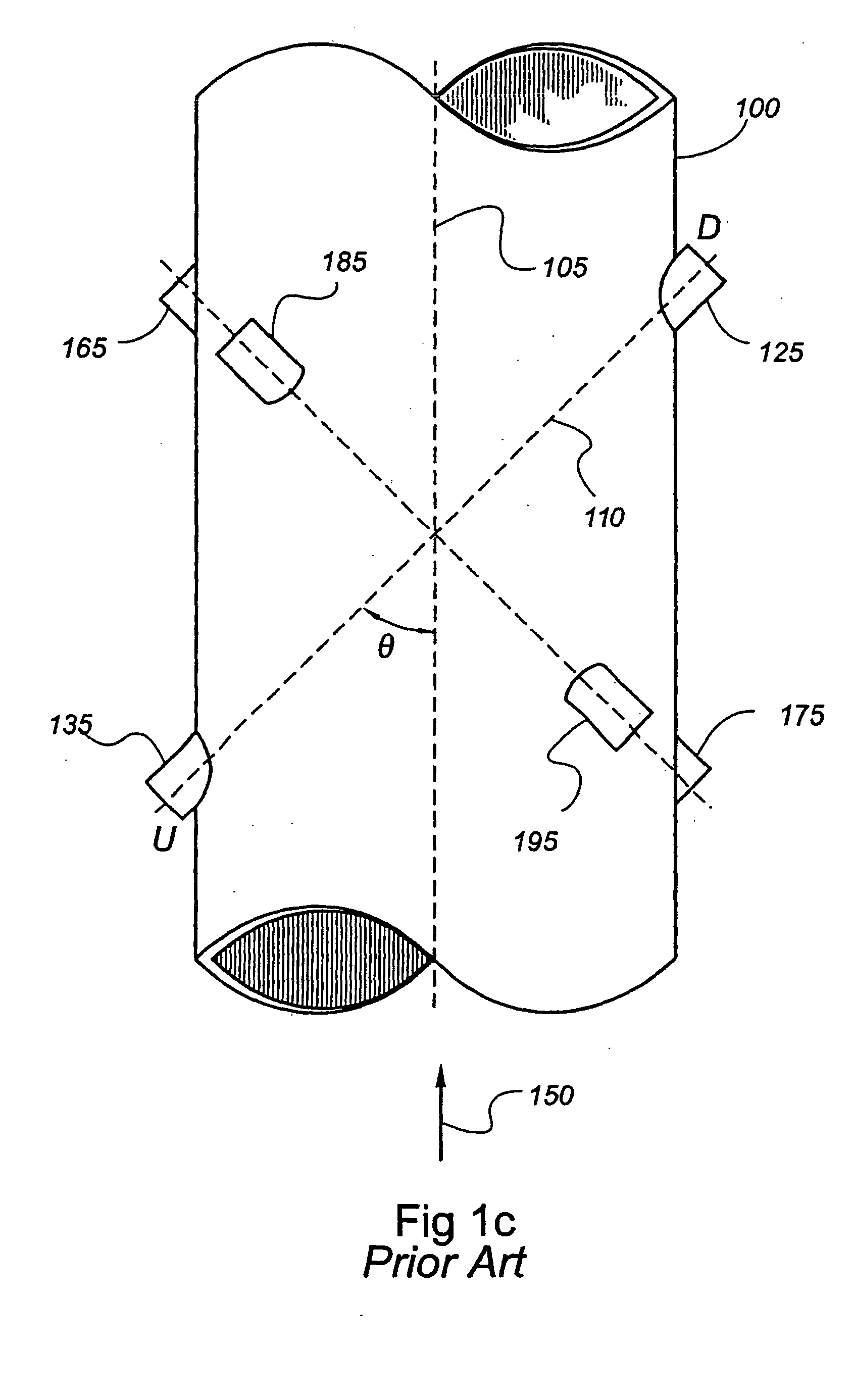
FIG. 1A shows one type of ultrasonic meter suitable for measuring gas flow. Spoolpiece 100, suitable for placement between sections of gas pipeline, has a predetermined size and thus defines a measurement section. Alternately, a meter may be designed to attach to a pipeline section by, for example, hot tapping. As used herein, the term “pipeline” when used in reference to an ultrasonic meter may be referring also to the spoolpiece or other appropriate housing across which ultrasonic signals are being sent. A pair of transducers 120 and 130, and their respective housings 125 and 135, are locate...


PUM


Abstract

A system and method is configured to take a “snapshot” of data received by a meter or measurement device so that it may be later frozen or duplicated in a manner identical to that of the meter. The system includes recording a continuous stream of raw data into a format suitable for transport to a site better suited for debug and diagnosis, and replaying the data on a replay device such that time, as seen by the system, may be “frozen” at will and any instant of the stream examined.

Description

CROSS-REFERENCE TO RELATED APPLICATIONS Not Applicable. STATEMENT REGARDING FEDERALLY SPONSORED RESEARCH OR DEVELOPMENT Not Applicable. BACKGROUND OF THE INVENTION The present invention relates generally to diagnosis of problems with measurements from a measurement device. More specifically, the invention relates to a method for the diagnosis of measurements from measurement devices that have a relatively high data input rate and a relatively low data output rate. Quite often, a physical property, characteristic, or phenomenon requires measurement. Various meters and measurement devices have been developed in a wide variety of industries to measure a characteristic-of-interest. For example, a person may wish to measure characteristics of the atmosphere, a fluid flow, or a moving object. Measurement devices to monitor fluid flow include ultrasonic meters, coreolis meters, magnetic flow meters, turbine meters, and orifice plates. Measurement devices are not perfect, however. They...

Claims


Application Information

Patent Timeline
Patent Type & Authority Applications(United States)
IPC IPC(8): G01F1/66G01F15/06G01F25/00G06FG06F11/30
CPCG01F1/667G01F25/0007G01F15/063G01F1/668G01F25/10
Inventor MALIK, VIPINMURRAY, GAIL P.BHATT, ABHISHEK
Owner MICRO MOTION INC
Why Eureka
Try Eureka