Roller bearing and method of assembling the same

a technology of roller bearings and rollers, which is applied in the direction of needle bearings, shafts and bearings, rotary machine parts, etc., can solve the problems of high cost of rollers, and the tendency of frictional wear of roller end faces to be prominent, so as to increase the number of rollers, reduce the deformation of roller retainers, and reduce the cost of rollers

Inactive Publication Date: 2010-08-03
NTN CORP
View PDF51 Cites 10 Cited by
  • Summary
  • Abstract
  • Description
  • Claims
  • Application Information

AI Technical Summary

Benefits of technology

[0018]Accordingly, the present invention has been devised to substantially eliminate the various problems and inconveniences inherent in the full complement roller bearing and is intended to provide an improved roller bearing utilizing a roller retainer, which has an excellent assemblability in the sense that the assembly line can be automated.

Problems solved by technology

However, since the full complement roller bearing makes no use of the roller retainer, it is often experienced that some or all of the rollers tend to separate or fall from the right position during the handling thereof prior to the full complement roller bearing being installed on a machine or equipment.
Since the opposite end faces of each roller are steepled or have the steeples, the frictional wear of the roller end faces tends to be prominent when the full complement roller bearing is employed in the environment where an induced thrust force is large.
Since the opposite end faces of each roller are steepled or have the steeples, the roller is costly as compared with the roller having flat end faces.
On the other hand, the second full roller bearing utilizing the thermally curable grease has the following problems:
The type of grease and the type of oil are limited.
However, even the full complement roller bearing of the suggested design has the following problems:
Since during the assemblage that portion of the roller retainer is radially deformed against its own elasticity, automation of the assembly line is difficult to achieve.

Method used


Image

  • Roller bearing and method of assembling the same
  • Roller bearing and method of assembling the same
  • Roller bearing and method of assembling the same

Examples


Embodiment Construction

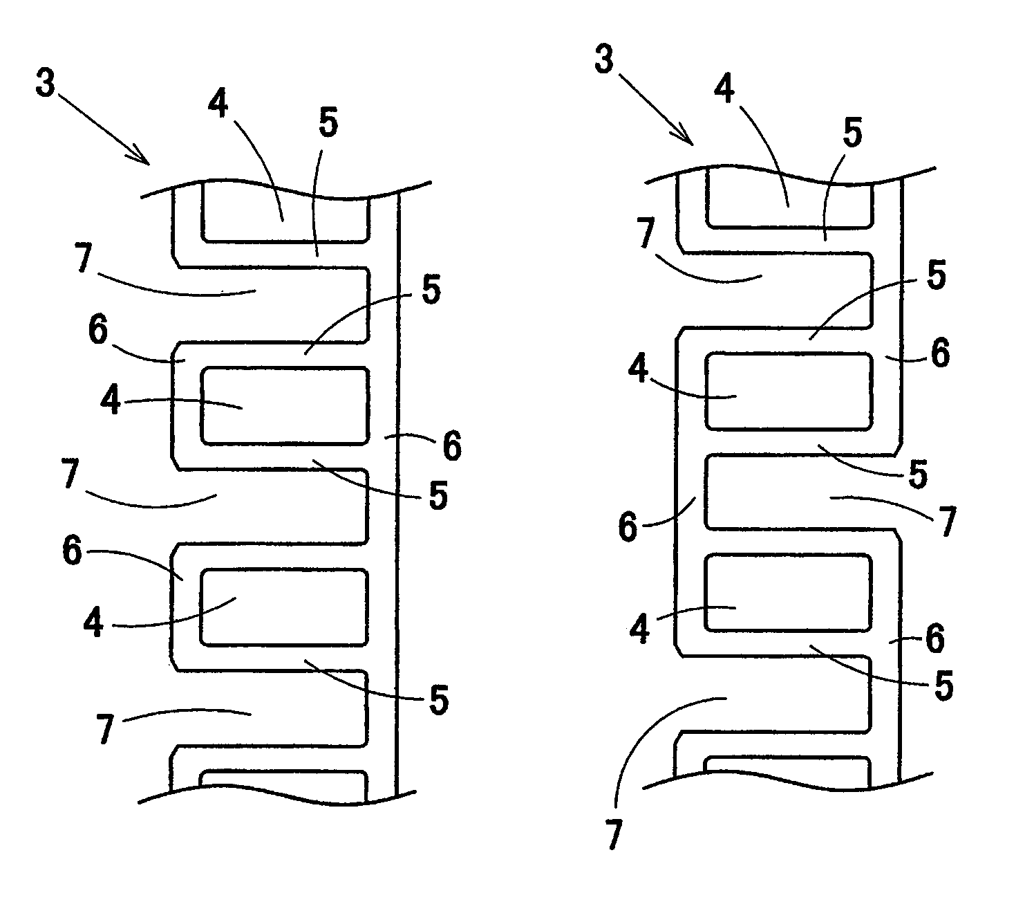
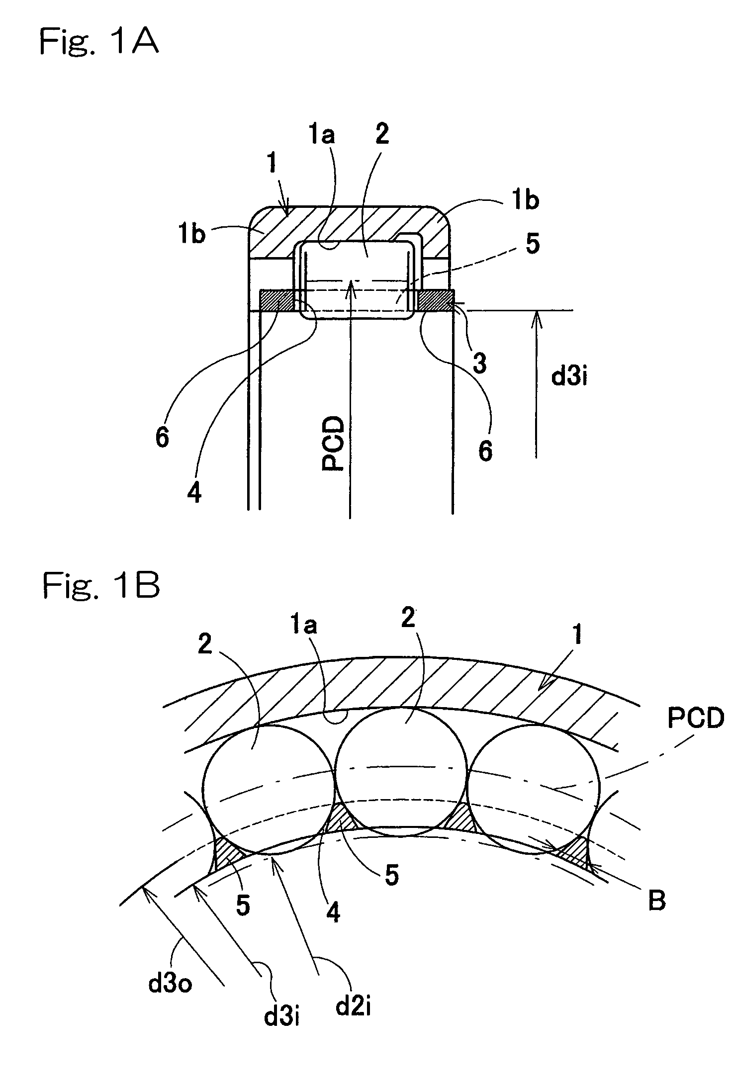
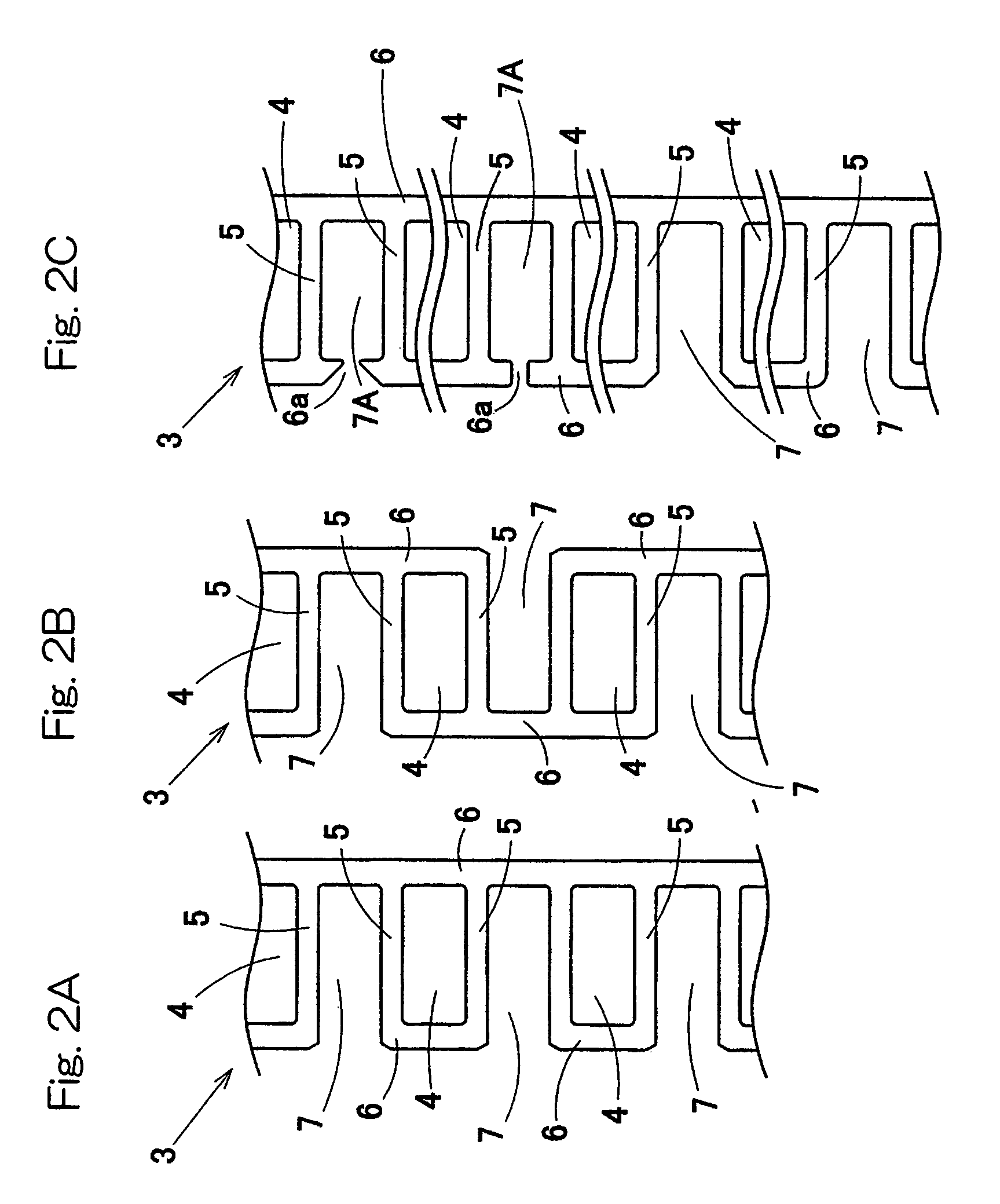
[0051]With particular reference to FIGS. 1 to 6, a roller bearing according to a first preferred embodiment of the present invention will be described in detail. The roller bearing includes an outer race 1 having an inner peripheral surface, a plurality of rollers 2 arranged in a circular row and held rollingly in contact with a raceway 1a defined by the inner peripheral surface of the outer race, and a ring-shaped roller retainer 3. The roller retainer 3 has pockets 4 spacedly defined in a direction circumferentially thereof so as to form a ladder-like structure or a step-like structure. The roller retainer 3 also has pillars 5 each defined between the neighboring pockets 4. Each pillar 5 is so positioned between the neighboring rollers 2 that the rollers 2 can be retained from a radially inner side of the roller bearing.

[0052]The outer race 1 has its opposite ends formed with radially inwardly extending collars 1b and is of a drawn cup type, that is, a shaped product made of a ste...


PUM


Abstract

A roller bearing utilizing a roller retainer, which has an excellent assemblability in the sense that the assembly line can be automated and which eliminates various problems inherent in the full complement roller bearing The roller bearing includes an outer race having a raceway, a plurality of rollers held in rolling contact with the raceway, and a ring-shaped roller retainer having a plurality of pockets, each rollingly receiving the respective roller, spacedly defined therein in a direction circumferentially thereof to form a ladder-like structure. The roller retainer has a plurality of slits that are spacedly defined in a direction circumferential thereof so as to extend from one axial end or the other axial end of the roller retainer to a position adjacent the other axial end or one axial end.

Description

BACKGROUND OF THE INVENTION[0001]1. Field of the Invention[0002]The present invention relates to a roller bearing equipped with a roller retainer, such as a needle roller bearing, which can be employed in an application similar to that in which the full complement roller bearing having an outer race is employed, and also relates to a method of assembling such roller bearing.[0003]2. Description of the Prior Art[0004]In the application where the outer diameter of the bearing is limited and, on the other hand, a relatively large load bearing capacity is required, the full complement roller bearings have hitherto been employed in general. Since the full complement roller bearing has no pillar intervening between the neighboring rollers, the number of rollers employed therein can be increased as compared with the retainer-equipped roller bearing and the load bearing capacity can therefore be increased.[0005]However, since the full complement roller bearing makes no use of the roller ret...

Claims


Application Information

Patent Timeline
Patent Type & Authority Patents(United States)
IPC IPC(8): F16C33/48F16C43/04F16C33/46F16C43/06F16C19/26F16C19/46F16C43/08
CPCF16C19/26F16C33/46F16C33/4635F16C43/08F16C2240/84F16C2300/02
Inventor KONO, SHINGOOBAYASHI, KOUSUKEAKAMATSU, HIDEKI
Owner NTN CORP
Why Eureka
Try Eureka