Polymer electrolyte fuel cell stack

a polymer electrolyte and fuel cell technology, applied in the direction of solid electrolyte fuel cells, fuel cells, fuel cell grouping, etc., can solve the problems of increasing the volume of the stack, excessive or insufficient fastening load, and increasing the thickness of the stack, so as to achieve easy simple structure, and easy change and adjustment of fastening load

Active Publication Date: 2011-12-01
PANASONIC CORP
View PDF4 Cites 24 Cited by
  • Summary
  • Abstract
  • Description
  • Claims
  • Application Information

AI Technical Summary

Benefits of technology

[0042]described above, according to the polymer electrolyte fuel cell stack of the present invention, it becomes possible to apply an appropriate and uniform load to the stack with a simple structure. Further, it becomes possible to change and adjust the fastening load with ease just by replacing with another pin member differing in dimension or shape or number of pieces in terms of the direction perpendicular to the longitudinal direction of the pin member(s). Accordingly, even there exist variations in thickness of the stacked product, for example, just by preparing a pin member(s) differing in dimension or shape or number of pieces in terms of the direction perpendicular to the longitudinal direction of the pin member(s), and replacing the pin member(s) thereby, the effect of easier adjustment of the fastening load and application of an appropriate and uniform, i.e., even, load to the stack can be exhibited. As a result, application of such a uniform load to the stack brings about the additional effect of improved power generation performance and durability of the stack. Further, since coupling is established with a simple structure made up of the coupling portions and the pin members, any space for providing a load adjustment mechanism of a complicated structure or the like can be dispensed with. Additionally, fastening of the stack can easily be carried out, and excellent assemblability can be achieved.

Problems solved by technology

Meanwhile, in a case where a stacked product structured by stacking modules each made up of a plurality of unit cells in one direction is fastened up with a band, the fastening load to the stacked product is determined by the thickness of the stacked product and the length of the band, and an appropriate fastening load cannot be applied to the entire stack.
Even in the methods employed in Patent Documents 1, 3, and 4, since fastening can only be carried out under residual stress previously loaded on the bands, they suffer from excessive or insufficient fastening load upon variations in thickness of the stacked product.
Similarly, Patent Document 6 is only capable of achieving fastening under the residual stress which is loaded previously when coupling the plate members to each other, and hence it suffers from excessive or insufficient fastening load upon variations in thickness of the stacked product.
Further, though the methods employed in Patent Documents 2, 5, and 7 are capable of adjusting the load through the use of the bolts or the disk springs addressing the variations in thickness of the stacked product, they suffer from an issue of an increase in volume of the stack, which is attributed to the bolts for the adjustment.

Method used


Image

  • Polymer electrolyte fuel cell stack
  • Polymer electrolyte fuel cell stack
  • Polymer electrolyte fuel cell stack

Examples


first working example

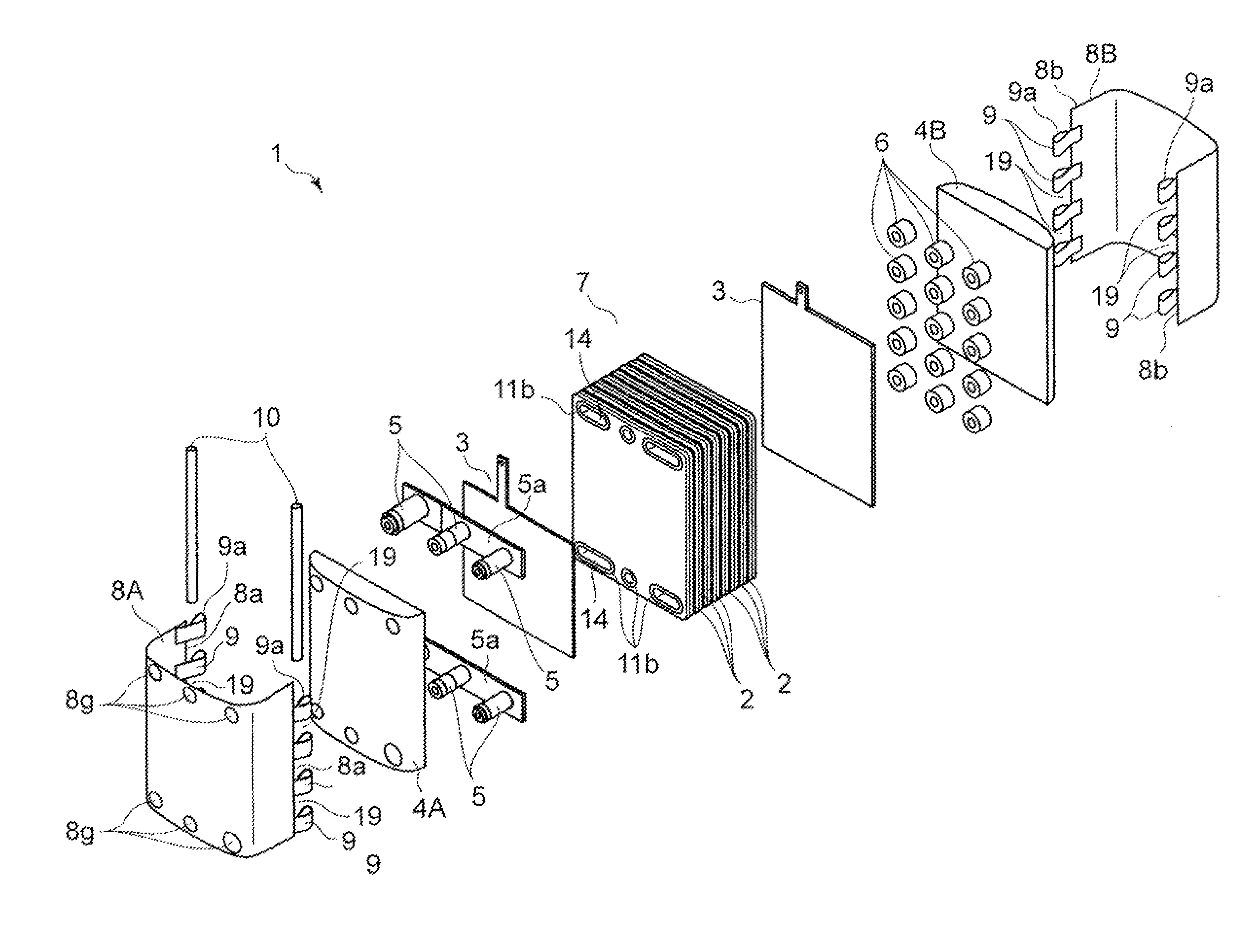
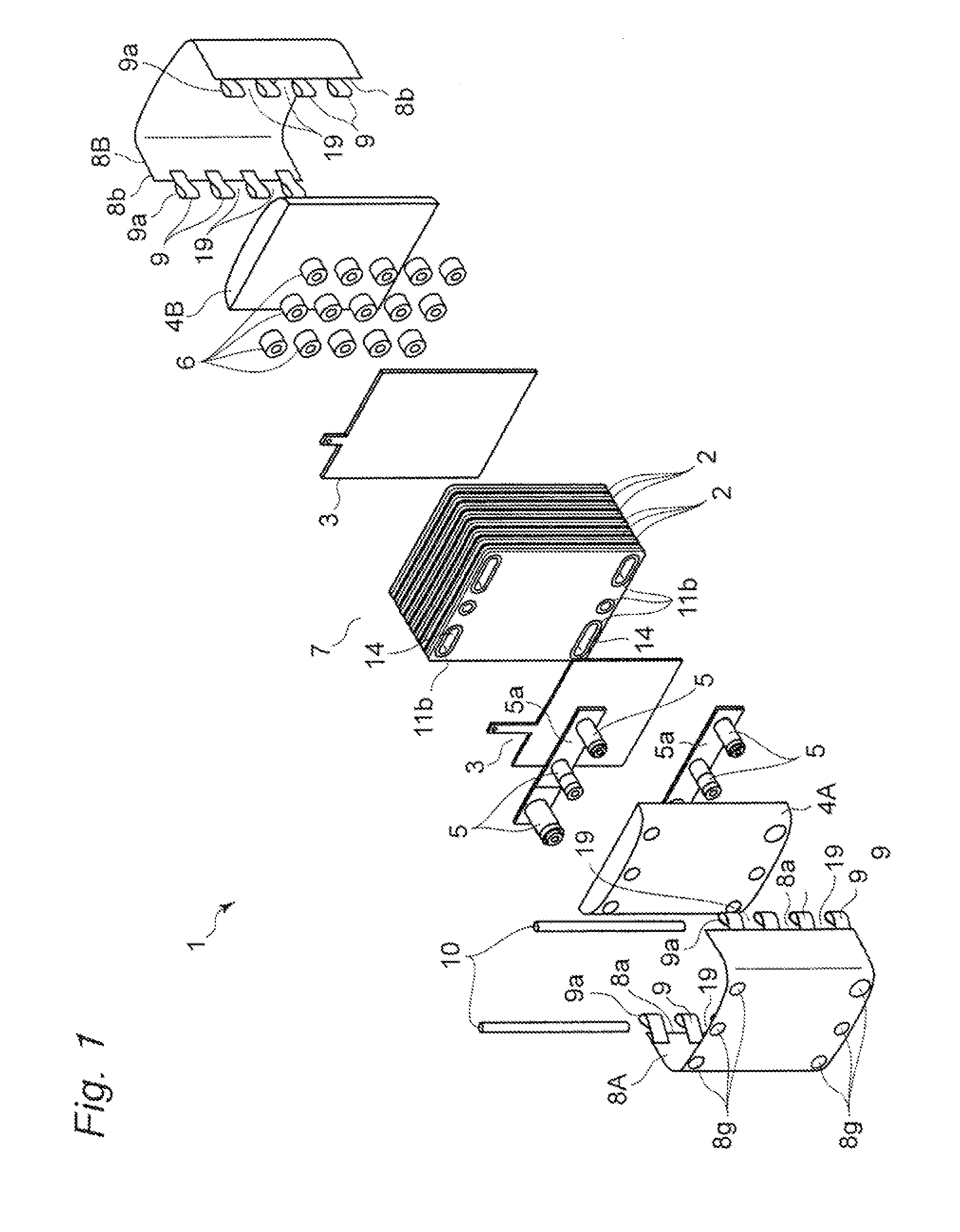
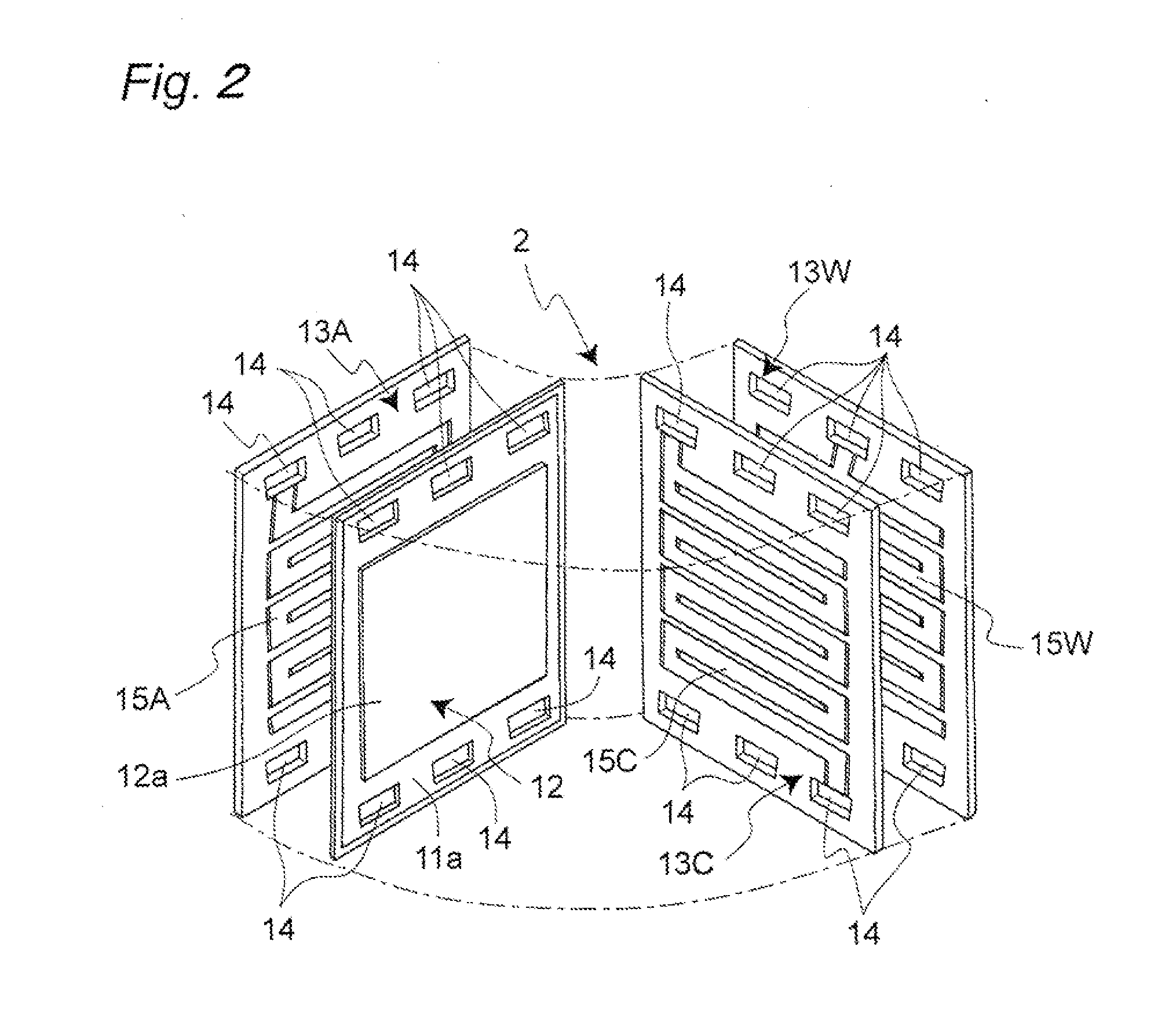
[0077]FIGS. 3A and 3B show cross-sectional plan views of fuel cell stacks 1 according to a first working example of the present embodiment and according to a variation example thereof, respectively. Current collecting plates 3 are disposed at the top and bottom surfaces of a cell-stacked product 7, respectively. Pipes 5 are disposed near one of the current collecting plates 3 on the bottom side of the cell-stacked product 7 and held by an end plate 4A. On the other one of the current collecting plates 3 on the top side, a multitude of internal springs 6 are disposed. Thus, such components are sandwiched between the top and bottom end plates 4A and 4B. The entire fastening target members are covered by two bands 8A and 8B which have band body portions 8c and 8d, respectively, which are as wide as the cell 2. As one example, fastening is established by the bands 8A and 8B being coupled by two pins 10. When the assembly is completed with the bands 8A and 8B and the pins 10, a multitude...

second example

[0106]The cross-section of each pin 10 is not limited to circular as in the first working example, and may be in any shape. In the following, a description will be given of shapes except for circular. For example, (1) in FIG. 8 is a cross-sectional plan view, which is identical to (1) in FIG. 6 for the purpose of comparison, showing a state where the coupling portions 9 are coupled using the pin 10A having a circular cross-sectional shape according to the first working example.

[0107]In contrast, (2) in FIG. 8 shows an enlarged cross-sectional plan view of the coupling portions 9 of the bands 8 and a pin 10E according to the second working example. As the pin 10E used herein, a rod whose cross section taken perpendicularly to its longitudinal direction is oval is used. In the second working example, the pin 10E whose cross section is oval, in which the long axis direction is twice as long as the short axis direction, is used. As to the fastening load, the fastening load with an extra...

third example

[0109](4) in FIG. 8 shows an enlarged cross-sectional plan view around the coupling portions 9 of the bands 8 according to the third working example of the embodiment. Employing a plurality of pins 10G of the same type for fastening the coupling portions 9 of the bands 8, the fastening load can be adjusted. According to the third working example, when the thickness of the cell-stacked product 7 is thin, the pins 10G can be inserted into one coupling section of the coupling portions 9 and the coupling portions 9. That is, two pins 10G can be inserted into one through hole 9a formed of the coupling portions 9, so as to adjust the fastening load addressing the thickness variations of the cell-stacked product 7 by a length of the diameter of the pin 10G. This is effective in being capable of completing the stack assembly without incurring an increase in the volume of the stack 3 or requiring preparation of the pins 10 differing from one another in diameter and cross-sectional shape. Sin...


PUM

PropertyMeasurementUnit
thicknessaaaaaaaaaa
diameteraaaaaaaaaa
diameteraaaaaaaaaa

Abstract

When assembly is carried out by clamping a stacked product made up of a plurality of unit cell modules, paired end plates respectively disposed on both the sides thereof and the like by a plurality of fastening members, first coupling portions of one end portion of each of such plurality of fastening members and second coupling portions of the other end portions are combined to each other, and coupled with one pin member. Thus, a plurality of such fastening members are coupled.

Description

TECHNICAL FIELD[0001]The present invention relates to a solid polymer electrolyte fuel cell stack of an ambient temperature operating type used for a portable power supply, an electric vehicle-use power supply, a household cogeneration system, or the like.BACKGROUND ART[0002]A fuel cell using polyelectrolyte allows a hydrogen-containing fuel gas and an oxygen-containing oxidant gas such as air to electrochemically react with each other, such that electric power and heat are produced at the same time. The fuel cell is basically structured with a polymer electrolyte membrane that selectively transports hydrogen ions, and paired electrodes formed on both the surfaces of the polymer electrolyte membrane, i.e., an anode and a cathode, respectively. The electrodes each have a catalyst layer whose principal component is carbon powder bearing platinum metal catalyst and which is formed on the front surface of the polymer electrolyte membrane, and a gas diffusion layer which has combined fea...

Claims


Application Information

Patent Timeline
Patent Type & Authority Applications(United States)
IPC IPC(8): H01M8/24H01M8/10
CPCH01M8/247H01M8/2475Y02E60/50H01M2008/1095H01M8/248
Inventor YAMAMOTO, YOKO
Owner PANASONIC CORP
Why Eureka
Try Eureka