
Electric Power Steering Apparatus

a technology of electric power steering and electric motor, which is applied in the direction of electrical steering, mechanical energy handling, transportation and packaging, etc., can solve the problems of fluctuation in control accuracy and earth failure, and achieve the effects of improving electromagnetic compatibility, reducing the number of components, and improving the assemblability of electric power steering apparatus

Inactive Publication Date: 2009-07-23
NSK LTD
View PDF5 Cites 24 Cited by
  • Summary
  • Abstract
  • Description
  • Claims
  • Application Information

AI Technical Summary

Benefits of technology

[0004]Moreover, in a column-type electric power steering apparatus as the electric power steering apparatus, for example, as described in JP2004-131047A, a torque sensor including a magnetic sensor is incorporated in a column housing and a signal terminal of this torque sensor is directly connected to a control board to omit a signal line. In this way, in the column-type electric power steering apparatus, because the torque sensor including the magnetic sensor is incorporated in the column housing, it is necessary to ground the torque sensor to a vehicle body side using a ground harness exclusive for the column housing in order to improve EMC (electromagnetic compatibility) of a circuit system of the torque sensor. The ground harness for this purpose is necessary.
[0006]Therefore, the present invention has been devised in view of the unsolved problems of the examples in the past and it is an object of the present invention to provide an electric power steering apparatus in which ground processing for respective sections requiring a ground can be reduced to necessary minimum to improve assemblability and a fall in electromagnetic compatibility and fluctuation in control accuracy can be controlled.
[0016]According to the present invention, the control unit including the board mounted with the control circuit that controls to drive the electric motor is mounted on the reduction gear box, the connecting section of the electric motor is electrically connected to the control unit directly, and the connection of the reduction gear box and the control unit to the ground is performed via the grounding line disposed between the control unit and the power feeding unit. Therefore, since the reduction gear box and the control unit are grounded to the power feeding unit via the common ground line, there is an effect that it is possible to improve electromagnetic compatibility (EMC) of the reduction gear box and it is possible to reduce the number of components and man-hour and improve assemblability of the electric power steering apparatus.
[0017]Since the grounding paths between the control unit and the reduction gear box are formed via the conductive cover, it is possible to improve electromagnetic compatibility of the control unit itself.

Problems solved by technology

There is an unsolved problem in that, to earth the minus side of the bridge circuit, since it is necessary to connect an earth line to a vehicle body side member, this is bothersome and causes an earth failure.
Therefore, there is an unsolved problem in that assemblability of the electric power steering apparatus falls, a relative potential difference occurs because the ground wires in two routes are wired to different places of a vehicle, respectively, and a fall in electromagnetic compatibility (EMC) and fluctuation in control accuracy due to the occurrence of the earth potential difference occur.

Method used


Image

  • Electric Power Steering Apparatus
  • Electric Power Steering Apparatus
  • Electric Power Steering Apparatus

Examples


first embodiment

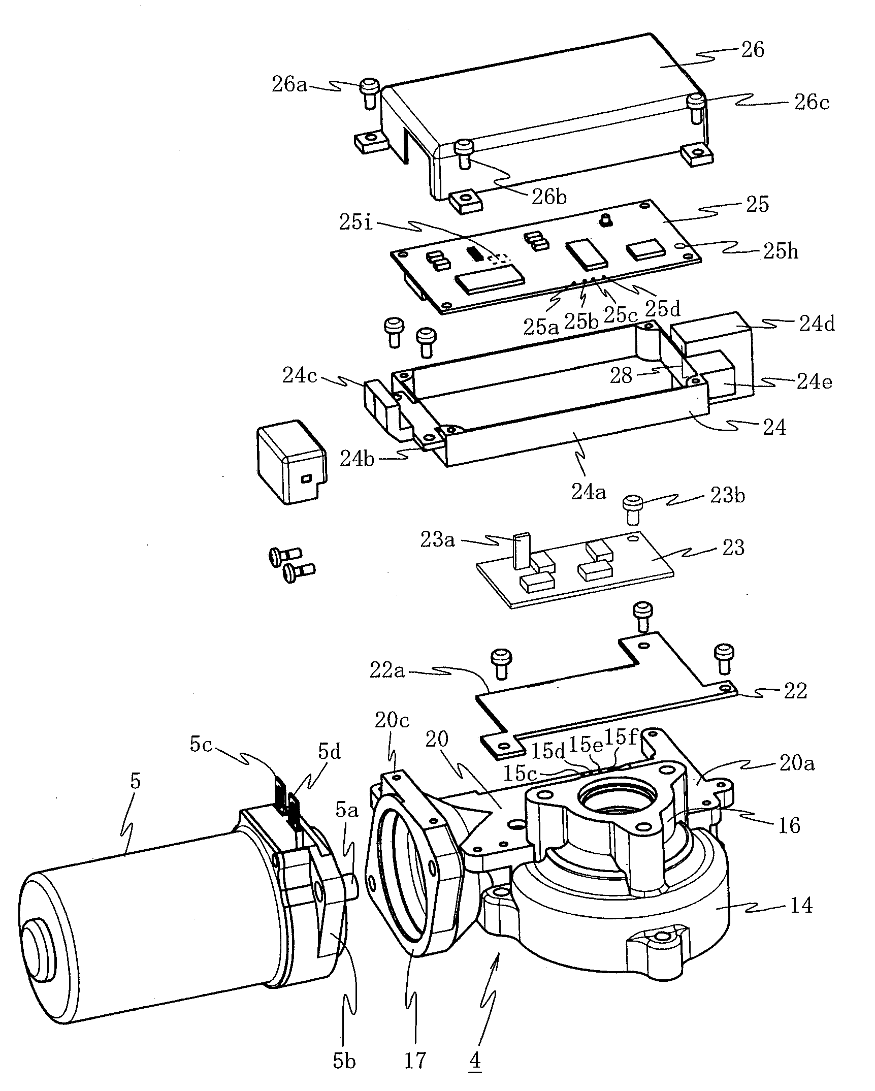
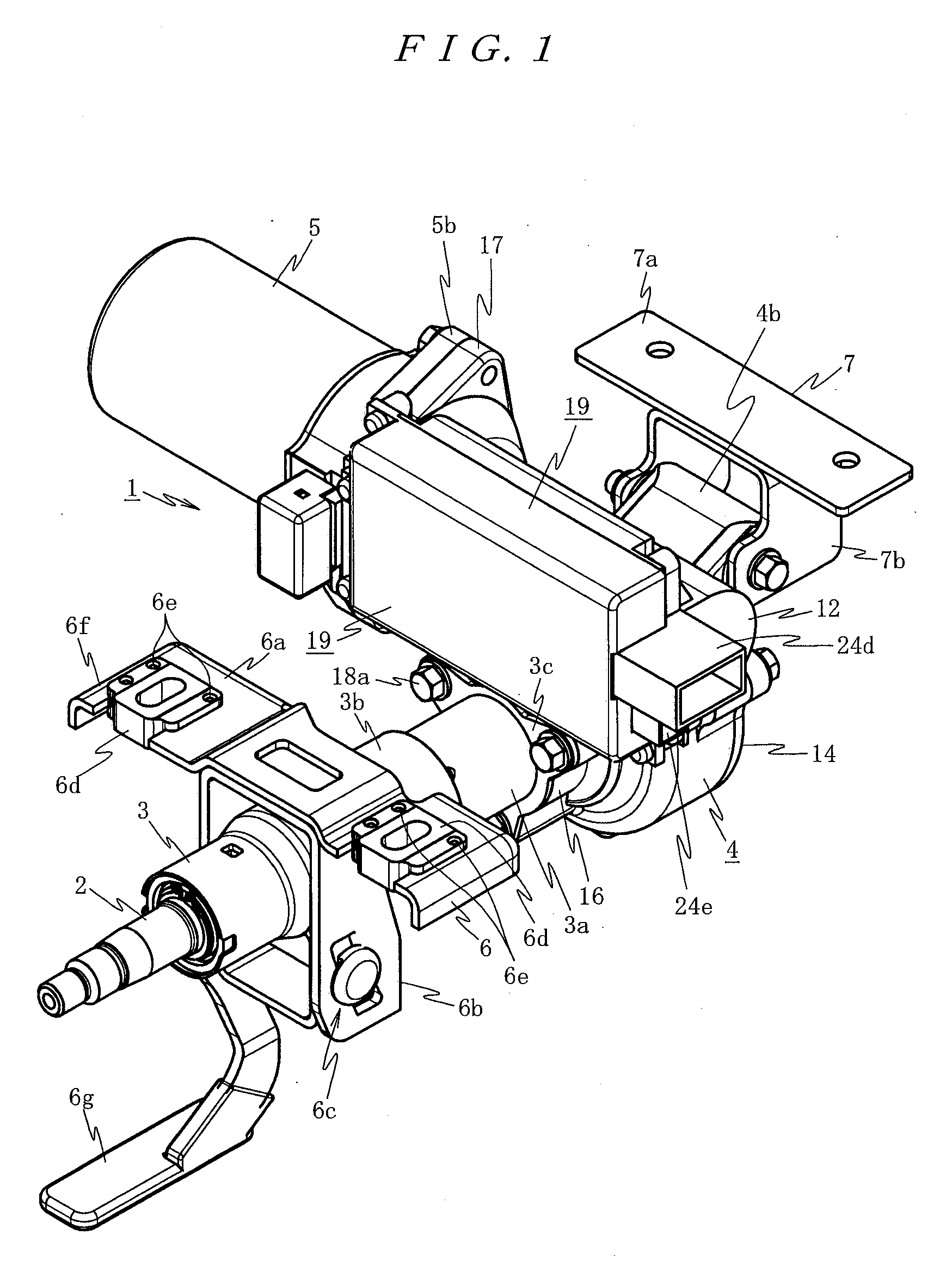
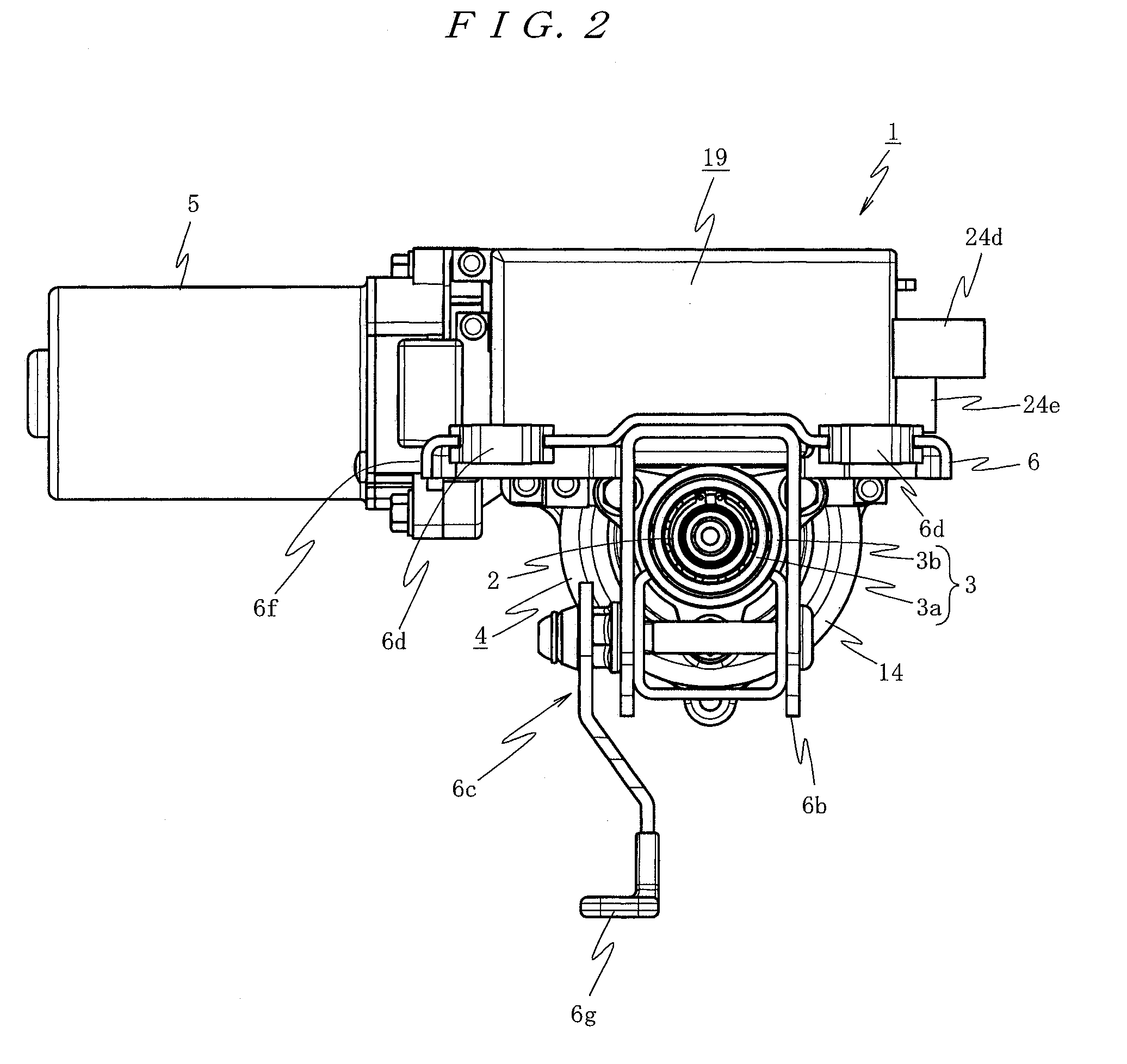
[0038]FIG. 1 is a perspective view showing an example of a case in which the present invention is applied to a right-hand drive car. FIG. 2 is a front view, FIG. 3 is a left side view, FIG. 4 is a plan view, and FIGS. 5 and 6 are disassembled perspective views of a main part of the example.

[0039]In FIG. 1, reference numeral 1 denotes a column-type electric power steering apparatus. A reduction gear box 4 is coupled to a steering column 3 in which a steering shaft 2 coupled to a steering wheel (not shown) is inserted rotatably. In this reduction gear box 4, an electric motor 5 including a brush motor, an axial direction of which is extended in a direction orthogonal to an axial direction of the steering column 3, is disposed.

[0040]The steering column 3 has, in a coupling section with the reduction gear box 4, a double tube structure including an inner tube 3a and an outer tube 3b for absorbing impact energy at the time of collapse and securing a predetermined collapse stroke. The out...

second embodiment

[0083]Next, the present invention is explained with reference to FIG. 17.

[0084]In this second embodiment, the grounding path between the control unit 19 and the reduction gear box 4 is a grounding path different from that in the first embodiment.

[0085]In other words, in the second embodiment, as shown in FIG. 17, the grounding path in the control unit 19 is a second grounding path different from the first grounding path in the first embodiment.

[0086]In this second grounding path, as shown in FIG. 17, the ground pin 28 of the power supply connector 24e is inserted through the through hole 25h of the control board 25 to ground the control board 25. A ground line 41 is formed from this through hole 25h to a connection terminal 40 provided on the surface of the control board 25. This connection terminal 40 is set in contact with conductive cover 26 to ground the conductive cover 26. The conductive cover 26 is mounted on the flat attaching surface 20a of the reduction gear box 4 via the ...


PUM


Abstract

To provide an electric power steering apparatus in which ground processing for respective sections requiring a ground can be reduced to necessary minimum to improve assemblability. An electric power steering apparatus includes a steering column 3 having inserted therein a steering shaft 2 to which steering torque is transmitted and an electric motor 5 that transmits a steering assisting force to the steering shaft 2 via a reduction mechanism in a conductive reduction gear box 4. A control unit 19 including boards 23 and 25 mounted with control circuits that control to drive the electric motor is mounted on the reduction gear box 4, a connecting section of the electric motor 5 is electrically connected to the control unit 19 directly, and connection of the reduction gear box 4 and the control unit 19 to a ground is performed via a grounding line 29 disposed between the control unit 19 and a power feeding unit 30.

Description

TECHNICAL FIELD[0001]The present invention relates to an electric power steering apparatus including a steering column having inserted therein a steering shaft to which steering torque is transmitted and an electric motor that transmits a steering assisting force to the steering column via a reduction mechanism in a reduction gear box.BACKGROUND ART[0002]As an electric power steering apparatus in the past, for example, as described in JP2005-329866A, JP2005-329867A, JP2005-329868A, and JP2005-329869A, there has been proposed an electric power steering apparatus in which a motor is housed in a part of a rack case or a steering gear box in which a rack shaft is slidably housed or mounted, a housing in which a control board for controlling to drive the motor is housed is formed in the rack case or the steering gear box, and, when the control board inserted from an opening of the housing is brought into contact with an attachment boss formed in a bottom portion opposed to the opening, a...

Claims


Application Information

Patent Timeline
Patent Type & Authority Applications(United States)
IPC IPC(8): B62D5/04H02K11/00H02K7/06
CPCB62D5/0406H02K5/225H02K11/0073H02K7/1166H02K7/06H02K11/33
Inventor SEKINE, TAKAAKIHYOUDOU, NAOKIKASHIMOTO, KEIJI
Owner NSK LTD
Learn More