Reconfigurable dual-band band-pass filter

A band-pass filter and dual-band technology, applied in the field of wireless communication, can solve the problem that there are no constant reconfigurable filters in two frequency bands, achieve flexible design and miniaturization, reduce processing difficulty, and overcome the problem of bandwidth changes. Effect

Inactive Publication Date: 2015-04-15
SOUTH CHINA UNIV OF TECH
View PDF4 Cites 28 Cited by
  • Summary
  • Abstract
  • Description
  • Claims
  • Application Information

AI Technical Summary

Problems solved by technology

The published prior art basically does not realize a reconfigurable filter with constant absolute bandwidth in both frequency bands

Method used


Image

  • Reconfigurable dual-band band-pass filter
  • Reconfigurable dual-band band-pass filter
  • Reconfigurable dual-band band-pass filter

Examples


Embodiment 1

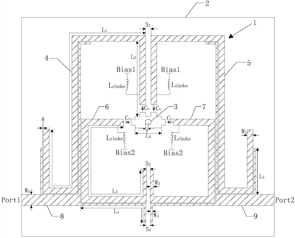
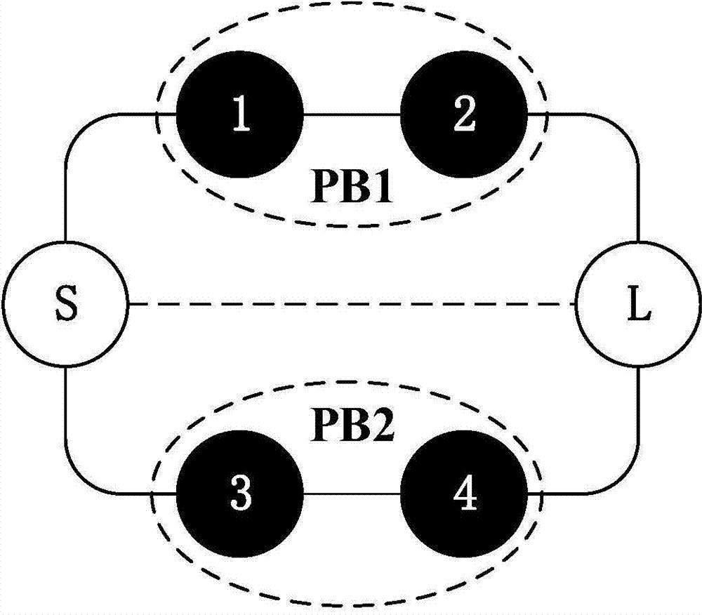
[0039] Such as figure 1 As shown, the reconfigurable dual-band bandpass filter of this embodiment includes an upper layer microstrip line structure 1, a middle layer dielectric substrate 2, a lower layer ground metal patch (not shown in the figure) and a metal via 3, so The metal through hole 3 runs through the microstrip line structure 1, the dielectric substrate 2 and the grounding metal patch in sequence, so that the microstrip line structure 1 and the grounding metal patch are connected through the dielectric substrate 2; the microstrip line structure 1 includes a second A resonator 4, a second resonator 5, a third resonator 6 and a fourth resonator 7, the first resonator 4 and the second resonator 5 adopt short-circuit end coupling (that is, magnetic coupling) after proper bending and folding A group of resonators is formed, and the third resonator 6 and the fourth resonator 7 adopt open end coupling (that is, electrical coupling) to form another group of resonators after...

Embodiment 2

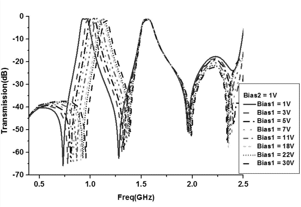
[0049] In this embodiment, a constant absolute bandwidth reconfigurable dual-band bandpass filter is designed. figure 1 On the basis of the structure, adjust the appropriate coupling coefficient k according to formula (1) i,j To achieve the requirement of constant absolute bandwidth, adjust the coupling strength of the end to the external quality factor Q e Perform a certain matching compensation, adjust the source-load coupling strength to change the zero point position of the out-of-band transmission, and improve the selectivity of the filter. The circuit and electromagnetic simulation software of this embodiment is Agilent Advanced Design System (ADS). The constant absolute bandwidth reconfigurable dual-band bandpass filter is selected and processed on a dielectric substrate with a dielectric constant of 2.55, a thickness of 0.8mm, and a loss tangent of 0.0029. The specific physical dimensions are shown in Table 1 below. Figure 7 The simulation and measurement results of...


PUM


Abstract

The invention discloses a reconfigurable dual-band band-pass filter which comprises an upper microstrip line structure, a middle dielectric substrate, a lower grounding metal patch and a metal through hole, wherein the metal through hole penetrates through the microstrip line structure, the dielectric substrate and the grounding metal patch in sequence to enable the microstrip line structure to be connected with the grounding metal patch through the dielectric substrate; the microstrip line structure comprises a first resonator, a second resonator, a third resonator and a fourth resonator; the first resonator and the second resonator are coupled to form a group of resonators after being folded; the third resonator and the fourth resonator are coupled to form another group of resonators after being folded; through the two groups of resonators, the microstrip line structure integrally forms a grid-shaped structure; one end of each resonator is loaded with a variable capacitance diode. According to the reconfigurable dual-band band-pass filter provided by the invention, the integration level and the electromagnetic compatibility of the system are improved; two pass bands are independently reconfigurable and the absolute bandwidth is basically constant, so that the application requirement of the conventional dual-band wireless communication system can be better satisfied.

Description

technical field [0001] The invention relates to a band-pass filter, in particular to a reconfigurable dual-band band-pass filter, which belongs to the field of wireless communication. Background technique [0002] With the continuous development of wireless communication technology, reconfigurable filters have attracted more and more attention from researchers. Not only because it can reduce the volume and cost of the system, but also because of its good electromagnetic compatibility, it can meet different system requirements. On the one hand, reconfigurable filters with constant absolute bandwidth play an important role in practical applications. On the other hand, in order to utilize limited spectrum resources most efficiently, more and more wireless systems work in dual frequency bands. The reconfigurable dual-band bandpass filter with constant absolute bandwidth has the characteristics of independent reconfigurability of dual passbands and relatively constant bandwidth...

Claims


Application Information

Patent Timeline
Patent Type & Authority Applications(China)
IPC IPC(8): H01P1/203H01P7/08
Inventor 褚庆昕陈志涵
Owner SOUTH CHINA UNIV OF TECH
Why Eureka
Try Eureka