A Reconfigurable Dual-Band Band-Stop Filter

A band-stop filter and dual-band technology, which is applied to waveguide devices, electrical components, circuits, etc., can solve the problem that there are no two frequency bands with constant absolute bandwidth, and achieve flexible and miniaturized design, good electromagnetic compatibility, and improved The effect of integration

Inactive Publication Date: 2017-10-20
SOUTH CHINA UNIV OF TECH
View PDF3 Cites 0 Cited by
  • Summary
  • Abstract
  • Description
  • Claims
  • Application Information

AI Technical Summary

Problems solved by technology

In practical applications, there are more reconfigurable filters with constant absolute bandwidth, that is, the absolute bandwidth remains relatively constant during frequency tuning. The existing technologies that have been disclosed so far have basically not achieved a reconfigurable bandstop with constant absolute bandwidth in both frequency bands. filter

Method used


Image

  • A Reconfigurable Dual-Band Band-Stop Filter
  • A Reconfigurable Dual-Band Band-Stop Filter
  • A Reconfigurable Dual-Band Band-Stop Filter

Examples


Embodiment 1

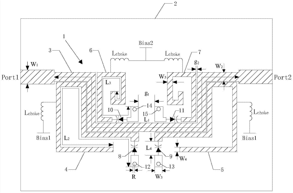
[0031] Such as figure 1As shown, the reconfigurable dual-band band rejection filter of this embodiment includes the upper microstrip line structure 1 and active circuit, the middle dielectric substrate 2, the lower ground metal patch (not shown in the figure) and the metal Through holes, the metal through holes sequentially pass through the microstrip line structure 1, the dielectric substrate 2 and the grounding metal patch, so that the microstrip line structure 1 and the grounding metal patch are connected through the dielectric substrate 2; the microstrip line structure 1 includes a main transmission line 3, a first resonator 4, a second resonator 5, a third resonator 6, and a fourth resonator 7. The main transmission line 3 is bent and folded into a structure with symmetrical left and right sides and a downward concave in the middle, so The first resonator 4 and the second resonator 5 are respectively arranged on the lower left and lower right of the main transmission line...

Embodiment 2

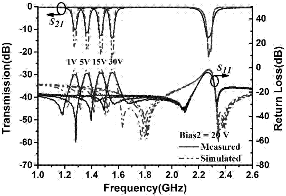
[0042] In this embodiment, a constant absolute bandwidth reconfigurable dual-band band-stop filter is designed. figure 1 Based on the structure, adjust the appropriate coupling coefficient k according to formula (1) i,j To achieve the requirement of constant absolute bandwidth, adjust the capacitance value of the varactor diode to change the stop band frequency and the equivalent magnetic coupling strength, so that the change trend of the total coupling strength meets the theoretical conditions. The circuit and electromagnetic simulation software of this embodiment is Agilent Advanced Design System (ADS). The constant absolute bandwidth reconfigurable dual-band band-stop filter is selected and processed on a dielectric substrate with a dielectric constant of 2.55, a thickness of 0.8mm, and a loss tangent of 0.0029. The specific physical dimensions are shown in Table 1 below.

[0043]

[0044] Table 1 Dimensions of reconfigurable dual-band bandstop filter

[0045] This emb...


PUM


Abstract

The invention discloses a reconfigurable dual-band band-stop filter, which comprises an upper-layer microstrip line structure and an active circuit, a middle-layer dielectric substrate, a lower-layer grounded metal patch, and metal through holes, and the metal through holes sequentially penetrate the micro The stripline structure, dielectric substrate and grounded metal patch, the microstrip line structure includes the main transmission line, the first resonator, the second resonator, the third resonator and the fourth resonator, the main transmission line is bent and folded into left and right symmetrical, middle With a concave structure, the first resonator and the second resonator are respectively arranged at the lower left and lower right of the main transmission line after bending and folding, and are coupled to form a group of resonators; the third resonator and the fourth resonator are in the After being bent and folded, it is set at the concave position in the middle of the main transmission line, and coupled to form another set of resonators; the short-circuit end of each resonator is loaded with a varactor diode. The filter of the present invention has a compact structure and realizes independent reconfigurability and constant absolute bandwidth of the two stopbands.

Description

technical field [0001] The invention relates to a band-stop filter, in particular to a reconfigurable dual-band band-stop filter with constant absolute bandwidth applied to a dual-frequency front-end system, belonging to the technical field of microwave communication. Background technique [0002] With the rapid development of information technology, wireless terminals with high integration density and multiple functions, small size, light weight, high stability, low cost and low power consumption have become the main research direction in the field of wireless communication. In the RF front-end, multi-frequency or tunable filters are the key components in multi-frequency / frequency-hopping transceivers, which can effectively filter out noise and various unwanted signals in each frequency band, reduce inter-channel interference, and achieve high-quality communication. In practical applications, reconfigurable filters with constant absolute bandwidth play a more important role...

Claims


Application Information

Patent Timeline
Patent Type & Authority Patents(China)
IPC IPC(8): H01P1/203
Inventor 褚庆昕陈志涵
Owner SOUTH CHINA UNIV OF TECH
Why Eureka
Try Eureka