
Flat panel display

a flat panel display and display panel technology, applied in the direction of static indicating devices, electric apparatus casings/cabinets/drawers, instruments, etc., can solve the problems of affecting the thermal characteristic of the display panel, the exposure of the flat panel display to internal electromagnetic interference, and the generation of radio waves that are harmful to the radio frequency spectrum. , to achieve the effect of improving the thermal characteristic and improving the resistance against the electromagnetic compatibility of the large flat panel display

Active Publication Date: 2011-03-17
SAMSUNG DISPLAY CO LTD
View PDF5 Cites 27 Cited by
  • Summary
  • Abstract
  • Description
  • Claims
  • Application Information

AI Technical Summary

Benefits of technology

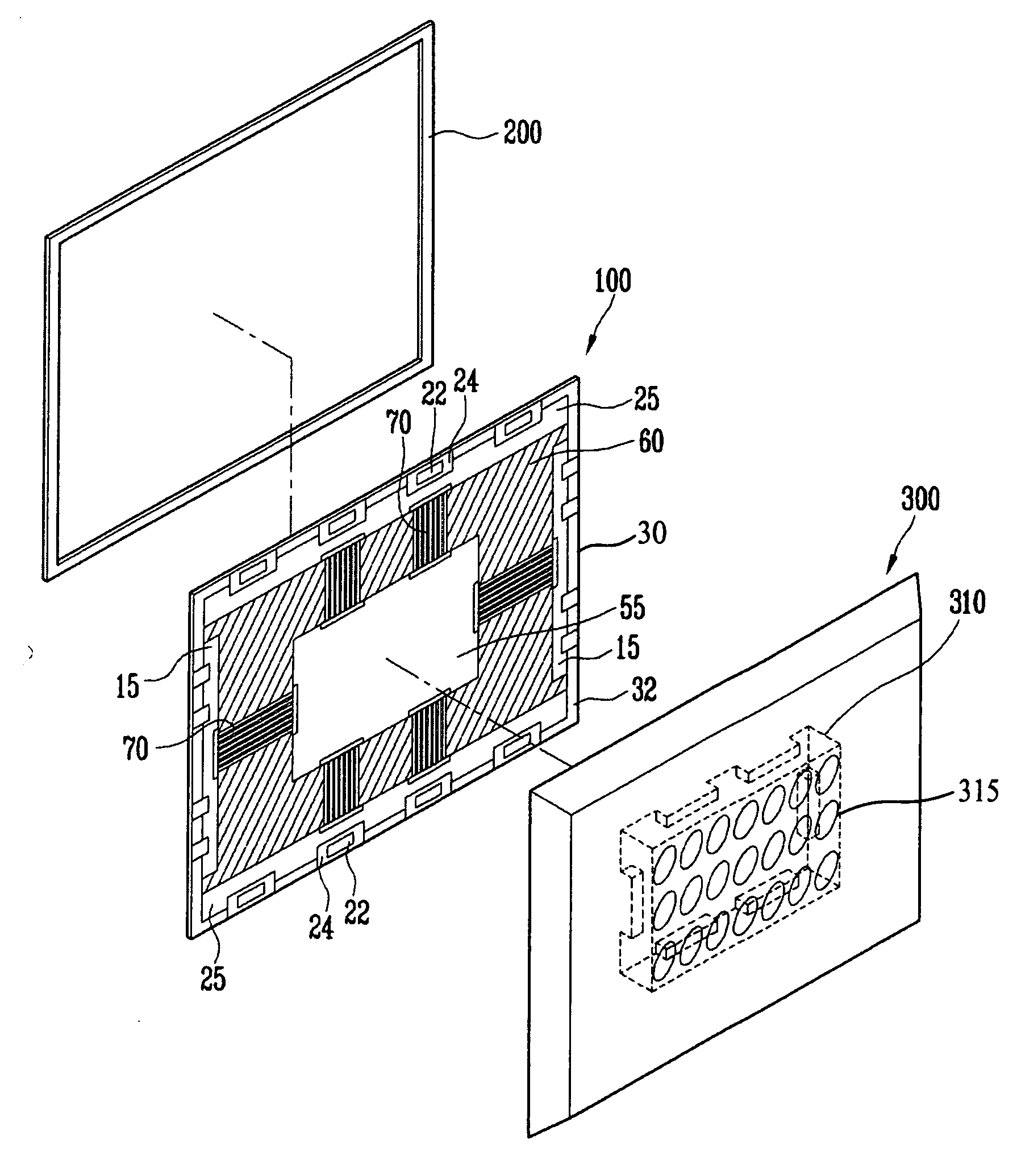
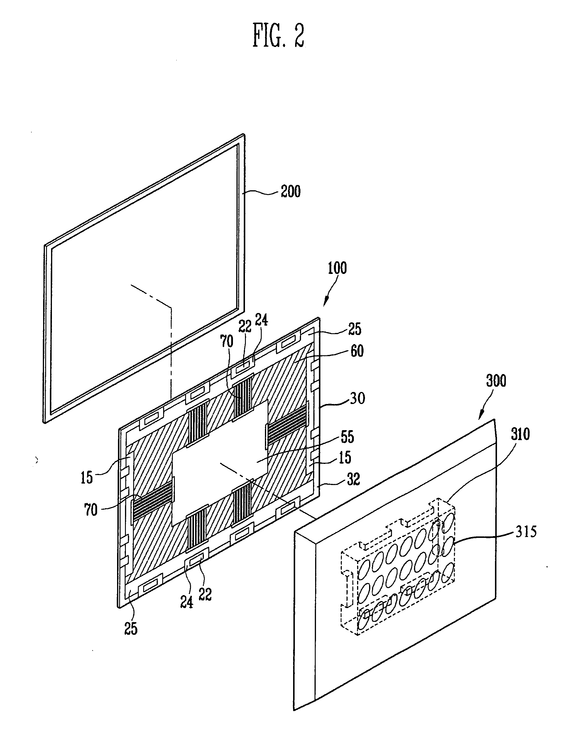
Accordingly, the present invention has been developed to provide a flat panel display (FPD) in which a conductive heat proof plate is inserted between the back surface of a display panel on which printed circuit boards (PCBs) and signal lines are formed; and in which a back frame positioned on the back surface of the display panel is provided to cover the printed circuit boards and the signal lines, in which a shield can is formed in the internal surface region of the back frame corresponding to the printed circuit board on which a timing controller is mounted, and in which the shield can is electrically coupled to the heat proof plate to improve resistance against the electromagnetic compatibility of a large flat panel display and to improve a thermal characteristic.
According to the present invention, the conductive heat proof plate is inserted into the bottom surface of the display panel on which the printed circuit boards and the signal lines are formed, the back frame positioned on the back surface of the display panel is provided to cover the printed circuit boards and the signal lines, the shield can is formed in the internal surface region of the back frame corresponding to the printed circuit board on which the timing controller is mounted, and the shield can is electrically coupled to the heat proof plate to improve the resistance against the electromagnetic compatibility of the large flat panel display and to improve the thermal characteristic.

Problems solved by technology

In the case of the flat panel display having the above structure, harmful radio waves are generated by the printed circuit boards, various elements mounted on the printed circuit boards, and the signal lines coupled between the printed circuit boards.
The generation of such radio waves is severely restricted.
However, the internal electromagnetic interference generated by various electronic elements which constitute the driver and the controller mounted on the printed circuit boards is excited by adjacent electronic elements by the metal back frame.
That is, the flat panel display is vulnerable to the internal electromagnetic interference.
In addition, in the case of the flat panel display having the above structure, since the printed circuit boards are directly attached on the back surface of the display panel by the adhesive tape, a path which can effectively disperse the heat generated by the display panel and the heat generated by the printed circuit board is not formed so that, when the flat panel display operates for a long time, the flat panel display is vulnerable to the heat.

Method used


Image

  • Flat panel display
  • Flat panel display
  • Flat panel display

Examples


Embodiment Construction

In the following detailed description, only certain exemplary embodiments of the present invention have been shown and described, simply by way of illustration. As those skilled in the art will realize, the described embodiments may be modified in various different ways, all without departing from the spirit or scope of the present invention. Accordingly, the drawings and description are to be regarded as illustrative in nature and not restrictive. In addition, when an element is referred to as being “on” another element, it can be directly on another element or be indirectly on another element with one or more intervening elements interposed therebetween. Also, when an element is referred to as being “connected to” another element, it can be directly connected to another element or be indirectly connected to another element with one or more intervening elements interposed therebetween. Hereinafter, like reference numerals refer to like elements.

Hereinafter, the exemplary embodiment...


PUM


Abstract

In a flat panel display (FPD), a conductive heat proof plate is inserted between the back surface of a display panel, on which printed circuit boards (PCBs) and signal lines are formed, and signal lines. A back frame positioned on the back surface of the display panel is provided to cover the printed circuit boards and the signal lines. A shield can is formed in the internal surface region of the back frame corresponding to the printed circuit board on which a timing controller is mounted. The shield can is electrically coupled to the heat proof plate to improve resistance against the electromagnetic compatibility of a large flat panel display and to improve a thermal characteristic.

Description

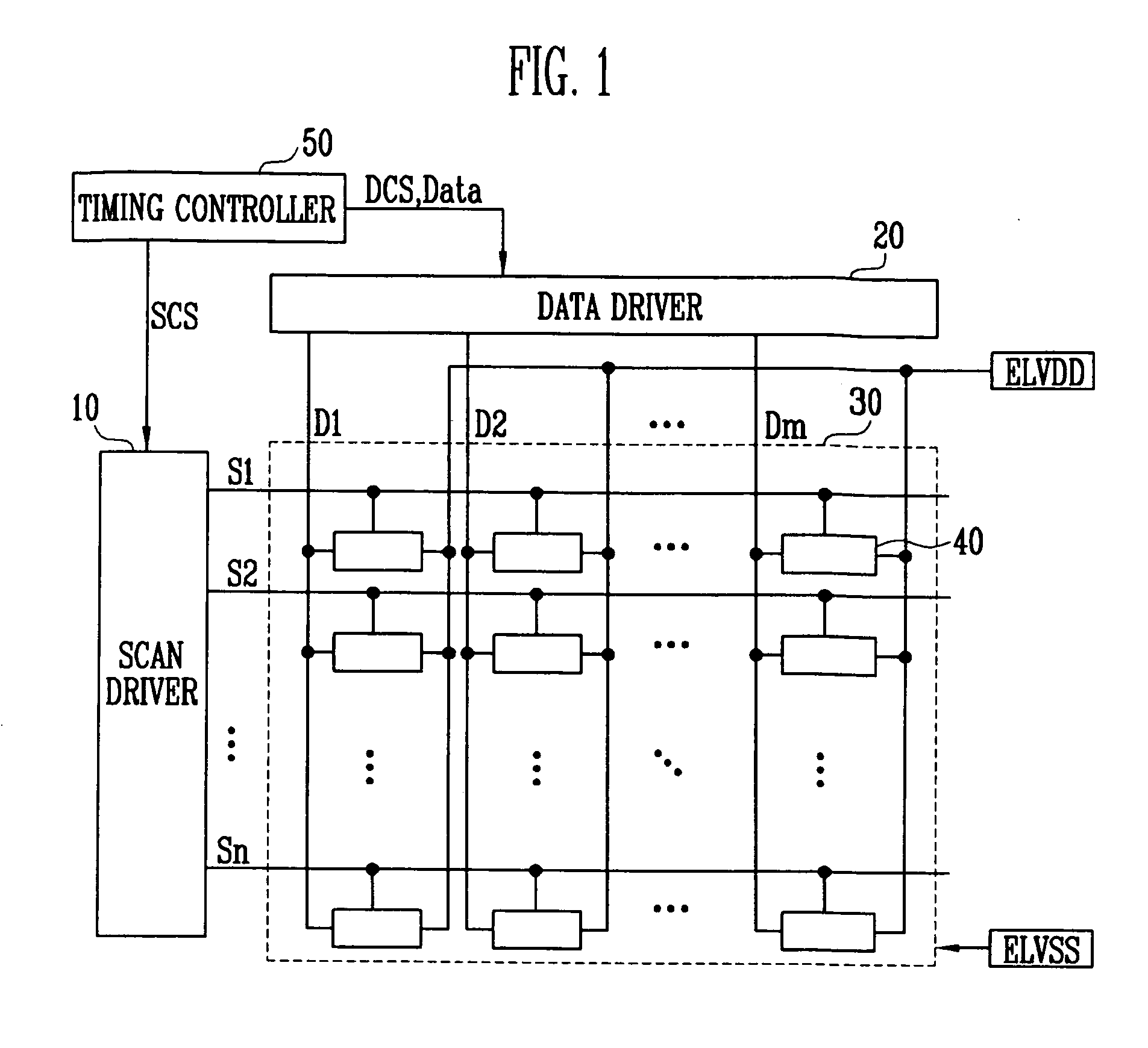
BACKGROUND OF THE INVENTION1. Field of the InventionThe present invention relates to a flat panel display (FPD) and, more particularly, to a flat panel display capable of effectively dispersing the heat generated by a panel, and a printed circuit board (PCB) and blocking electromagnetic interference (EMI) generated therein to improve resistance against electromagnetic compatibility (EMC).2. Description of the Related ArtA flat panel display (FPD) is divided into an emission type flat panel display, such as an organic light emitting display (OLED) and a plasma display panel (PDP); and a non-emission type flat panel display which does not emit light like a liquid crystal display (LCD).The flat panel display includes a display panel for displaying an image, a driver for providing a predetermined signal to the pixels provided in the display panel, and a controller for controlling the driver.In this regard, the driver and the controller are mounted on printed circuit boards (PCBs) and th...

Claims


Application Information

Patent Timeline
IPC IPC(8): H05K9/00G06F3/038H05K7/20H05B44/00
CPCG02F1/133382G02F1/133385G02F2001/133334H05K9/0054G06F1/20H05K7/20963H05K9/0037G06F1/1601Y02E10/549G02F1/133334H10K77/111
Inventor KIM, MIN-CHEOL
Owner SAMSUNG DISPLAY CO LTD
Learn More