Air cleaner for combustion engine

a technology for combustion engines and cleaners, applied in combustion-air/fuel-air treatment, separation processes, filtration separation, etc., can solve problems such as reducing sealability, and achieve the effect of improving air cleaning capability

Inactive Publication Date: 2005-01-11
KAWASAKI HEAVY IND LTD
View PDF32 Cites 23 Cited by
  • Summary
  • Abstract
  • Description
  • Claims
  • Application Information

AI Technical Summary

Benefits of technology

In view of the foregoing, the present invention has for its object to provide an improved air cleaner in which a cleaner element made of a soft material such as an urethane foam can retain its predetermined or required shape and can have an enhanced air cleaning capability.
According to the above described aspect of the present invention, since the cleaner element is formed to represent the heteromorphic shape, the cleaner element of a relatively large size can be installed while making a maximized utilization of the space available for the air cleaner while avoiding any possible interference with peripheral machine components around the air cleaner. Accordingly, the surface area of the cleaner element through which the air to be cleaned passes can advantageously be increased to thereby increase the cleaning capacity. Also, since the peculiar heteromorphic shape of the cleaner element can be retained by the retainer plates bonded respectively to the upper and lower end faces of the cleaner element, the deformation in shape of the cleaner element even though made of a urethane foam is prevented effectively by the retainer plate, resulting advantageously in increase of the assemblability and an inexpensive and simplified structure.
According to such another aspect of the present invention, since the cleaner element can be retained to a predetermined shape by means of the retainer plates bonded respectively to the upper and / or lower end faces of the cleaner element, formation of the cleaner element to a heteromorphic shape effective to achieve a maximized utilization of a space available for the air cleaner is effective to increase the cleaning capability by increasing the surface area of the cleaner element through which the air to be cleaned passes, even though the cleaner element is of an inexpensive and simplified structure. Also, in this structural feature, the retainer plate is fitted to the cleaner element and, on the other hand, the holder assembly is provided with the seat element for receiving the retainer plate bonded to such at least one of the upper and lower end faces of the wall. Accordingly the sealing member sandwiched between the retainer plate and the seat element of the holder assembly does not directly contact the narrow end portion of the holder assembly such as observed in the conventional air cleaner. Avoidance of the direct contact between the sealing member and the narrow end portion of the holder assembly is effective to avoid a permanent set of the sealing member which would result from fatigue and, hence, to enhance the sealing capability.
Moreover, as the elastic material for the retainer plate, any material more robust against the fatigue-induced permanent set than any urethane foam can be employed and, therefore, the need to replace the cleaner element and the retainer plate bonded thereto at an early stage can be eliminated to allow the cleaner element to be used for a prolonged period of time.
In a preferred embodiment of the present invention, each of the retainer plate and the sealing member may be made of a rubber material. The use of the rubber material allows the sealing member to have a prolonged lifetime while exhibiting a high sealing capability and, hence, the cleaner element to which the sealing member is bonded can have a prolonged lifetime.

Problems solved by technology

However, since in this structure the cleaner element 83 and the first holder element 82a is held in direct contact with the sealing member 86 at one end of the first holder element 82a whose width is narrow, the sealing member 86 made of an urethane foam tends to quickly loose its own resiliency, resulting in decrease of the sealability.

Method used


Image

  • Air cleaner for combustion engine
  • Air cleaner for combustion engine
  • Air cleaner for combustion engine

Examples


first embodiment

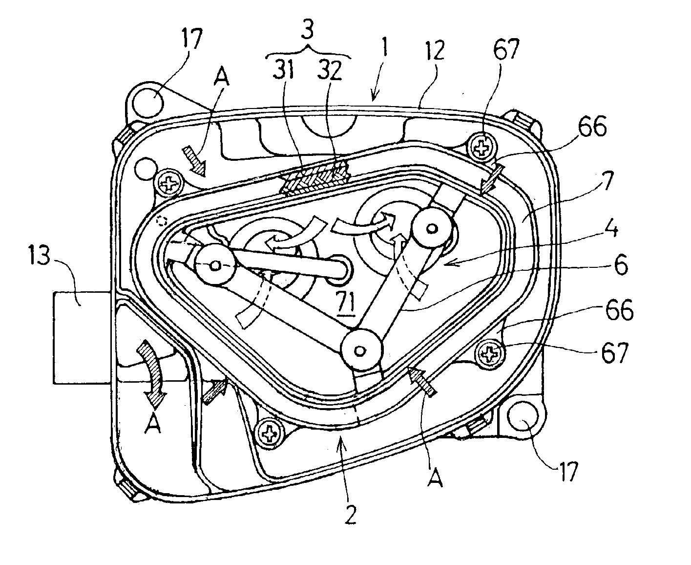
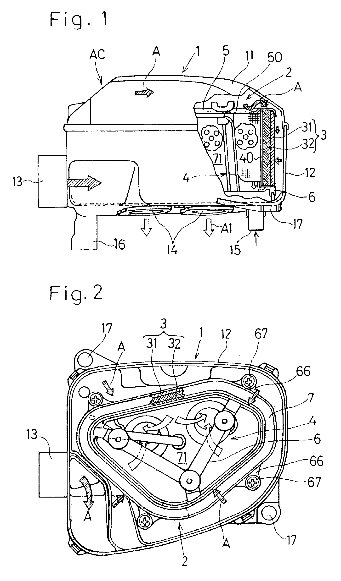
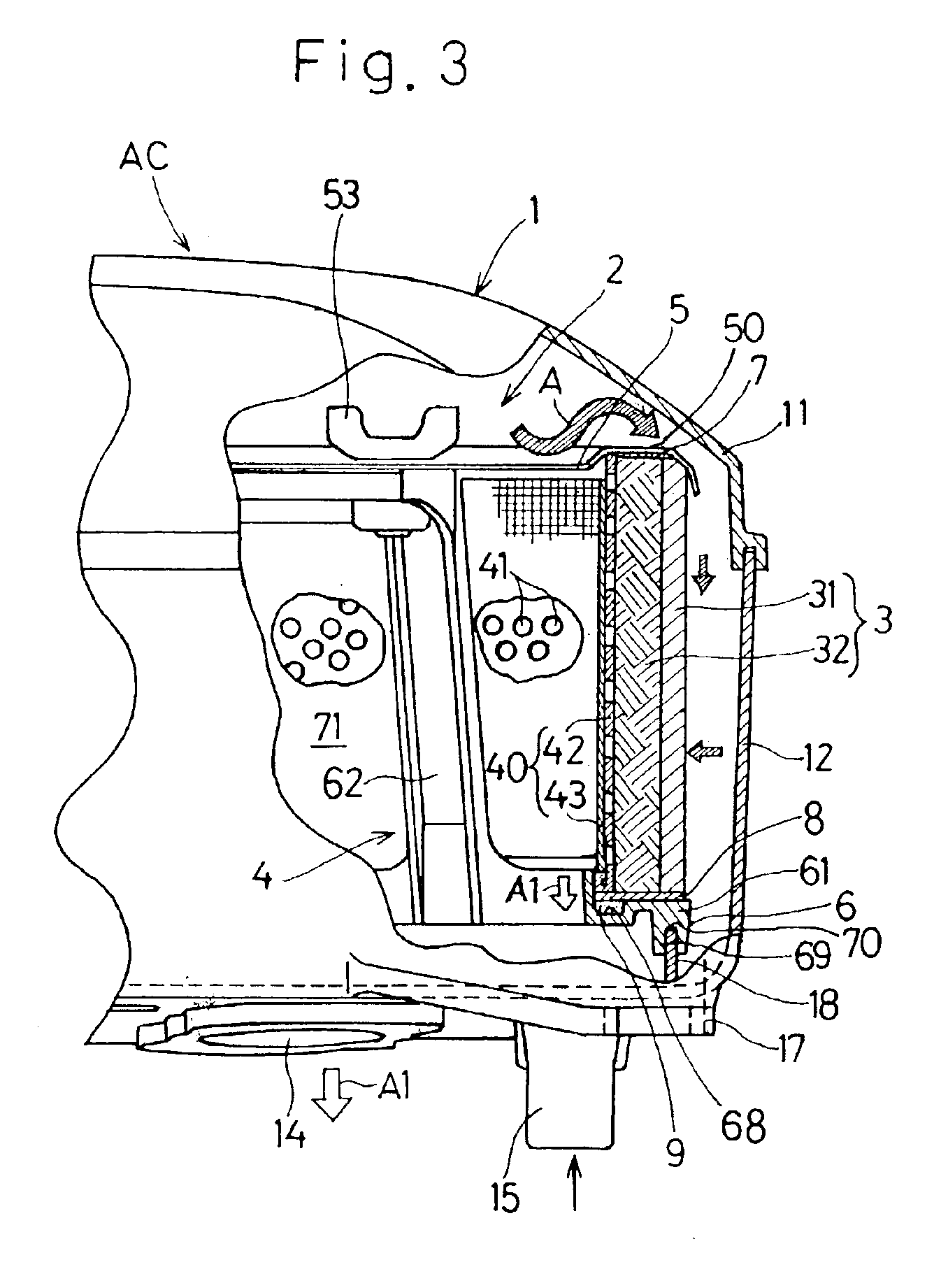
With respect to a lower side of the cleaner element 3, as is the case with that in the previously described first embodiment, an annular lower sealing member 9 is interposed and hence sandwiched between the second holder 6 and the second retainer plate 8 at the lower end face of the heteromorphic cleaner element 3 to thereby seal a gap between the lower side of the cleaner element 3 and the second holder 6. The annular lower sealing member 9 is disposed in the seat element 61 of the second holder 6 at a position confronting the lower end face of the tubular body 40A of the holder assembly 4 through the second retainer plate 8.

second embodiment

Also, in the present invention, the cleaner hood 11 has an outer peripheral portion depressed at a plurality of, for example, three locations to define shoulders 19. The shoulders 19 serve to hold down an abutment 56 which is also a seat element of the first holder 5. The shoulders 19 are defined at a plurality of, for example, three, locations in an outer side of the peripheral groove 55 in the outer peripheral portion of the first holder 5 to thereby engage the protrusion 18, that is rigid with the cleaner container 12, with the groove 69 in the support frame 61 of the second holder 6 through the sealing ring 70 so that the cleaner element assembly 2 of the previously described structure can be connected between the cleaner hood 11 and the container 12.

In the air cleaner AC of the structure described above, the cleaner element 3 having the retainer plates 7 and 8 bonded to the upper and lower end faces thereof, respectively, is mounted around the tubular body 40A with the first an...


PUM

PropertyMeasurementUnit
thicknessaaaaaaaaaa
elasticaaaaaaaaaa
gas permeabilityaaaaaaaaaa

Abstract

An air cleaner is provided which is effective to retain a cleaner element 3 in a heteromorphic shape and which has an increased cleaning capability and an assemblability. The air cleaner includes a cleaner element 3 made of a urethane foam and formed in a tubular form having an endless wall and operable to pass an air therethrough in a direction across the thickness of the cleaner element to purify the air. The cleaner element 3 when viewed from top represents a heteromorphic shape, and first and second retainer plates 7 and 8 made of an elastic material effective to retain the heteromorphic shape of the wall, which plates 7 and 8 are bonded to upper and lower end faces of the cleaner element 3. The cleaner element 3 together with the first and second retainer plates 7 and 8 is carried by a holder assembly 4 and is accommodated within a cleaner housing 1 together with the holder assembly 4. The holder assembly 4 includes a first holder having a seat element for holding the upper end face of the cleaner element 3 through the first retainer plate 7 and a second holder 6 having a seat element 61 for holding the lower end face of the cleaner element 3 through the second retainer plate 8.

Description

BACKGROUND OF THE INVENTION1. Field of the InventionThe present invention generally relates to an air cleaner and, more particularly, to the air cleaner for use with a motorcycle or the like for substantially purifying air being sucked into an internal combustion engine.2. Description of the Prior ArtThe air cleaner is generally of such a structure as shown in FIG. 6 which illustrates a conventional air cleaner in a side view with a portion cut out. Referring to FIG. 6, the illustrated air cleaner includes a cleaner housing 81, a filter holder 82 disposed within the cleaner housing 81, and an air cleaner element 83 retained by the filter holder 82. The cleaner housing 81 has an air intake port 84 and an air outlet port. An air A introduced into the cleaner housing 81 through the air intake port 84 passes through the cleaner element 83 which serves to remove a dust in the air. The air purified by the cleaner element 83 subsequently enters the engine (not shown) through the air outlet...

Claims


Application Information

Patent Timeline
Patent Type & Authority Patents(United States)
IPC IPC(8): B01D46/10F02M35/16B01D39/16B01D46/00B01D46/24F02M35/024
CPCB01D39/1676B01D46/0005B01D46/2403Y10S55/42B01D2275/10B01D2279/60
Inventor KUJI, YASUHIRONISHIKAWA, ISAMUKAWAMOTO, YUICHIWATANABE, KOUJI
Owner KAWASAKI HEAVY IND LTD
Why Eureka
Try Eureka