Electronically controlled actuator

a technology of electric actuators and actuators, applied in the direction of electrical apparatus, dynamo-electric machines, combustion engines, etc., can solve the problems of increasing the power consumption of the motor, shortening the lifetime of the motor, and complicated configuration, so as to improve the assembly and reduce the radiation heat of the turbo charger

Active Publication Date: 2013-02-28
MITSUBISHI ELECTRIC CORP
View PDF5 Cites 24 Cited by
  • Summary
  • Abstract
  • Description
  • Claims
  • Application Information

AI Technical Summary

Benefits of technology

[0008]However, Patent Document 1 does not refer to a arranged position of the motor which is especially susceptible to heat among the elements of the electronically controlled actuator, and therefore, the temperature of the motor may rise depending on the arranged position of the motor to shorten remarkably the lifetime of the motor.
[0010]The present invention has been made to solve the aforementioned problems, and an object of the invention is to provide an electronically controlled actuator that reduces the radiation heat from a turbo charger to a motor and improves the assemblability by an efficient arrangement of parts.
[0012]According to the invention, the following electronically controlled actuator can be provided: when the motor is arranged on the open top side of the actuator housing attached to the compressor housing, the motor can be located away from the turbine housing, so that the radiation heat from the turbo charger can be reduced, and also the attachment of the cover is guided with the motor support post to improve the assemblability.

Problems solved by technology

However, Patent Document 1 does not refer to a arranged position of the motor which is especially susceptible to heat among the elements of the electronically controlled actuator, and therefore, the temperature of the motor may rise depending on the arranged position of the motor to shorten remarkably the lifetime of the motor.
In addition, due to a configuration in which the control board, the motor, and the reduction gear mechanism are housed individually in separate housings, and these housings are fastened with screws to be integrated, there is also a problem such that the configuration is complicated and has a great number of parts, which takes time in the assembly.

Method used


Image

  • Electronically controlled actuator
  • Electronically controlled actuator
  • Electronically controlled actuator

Examples


embodiment 1

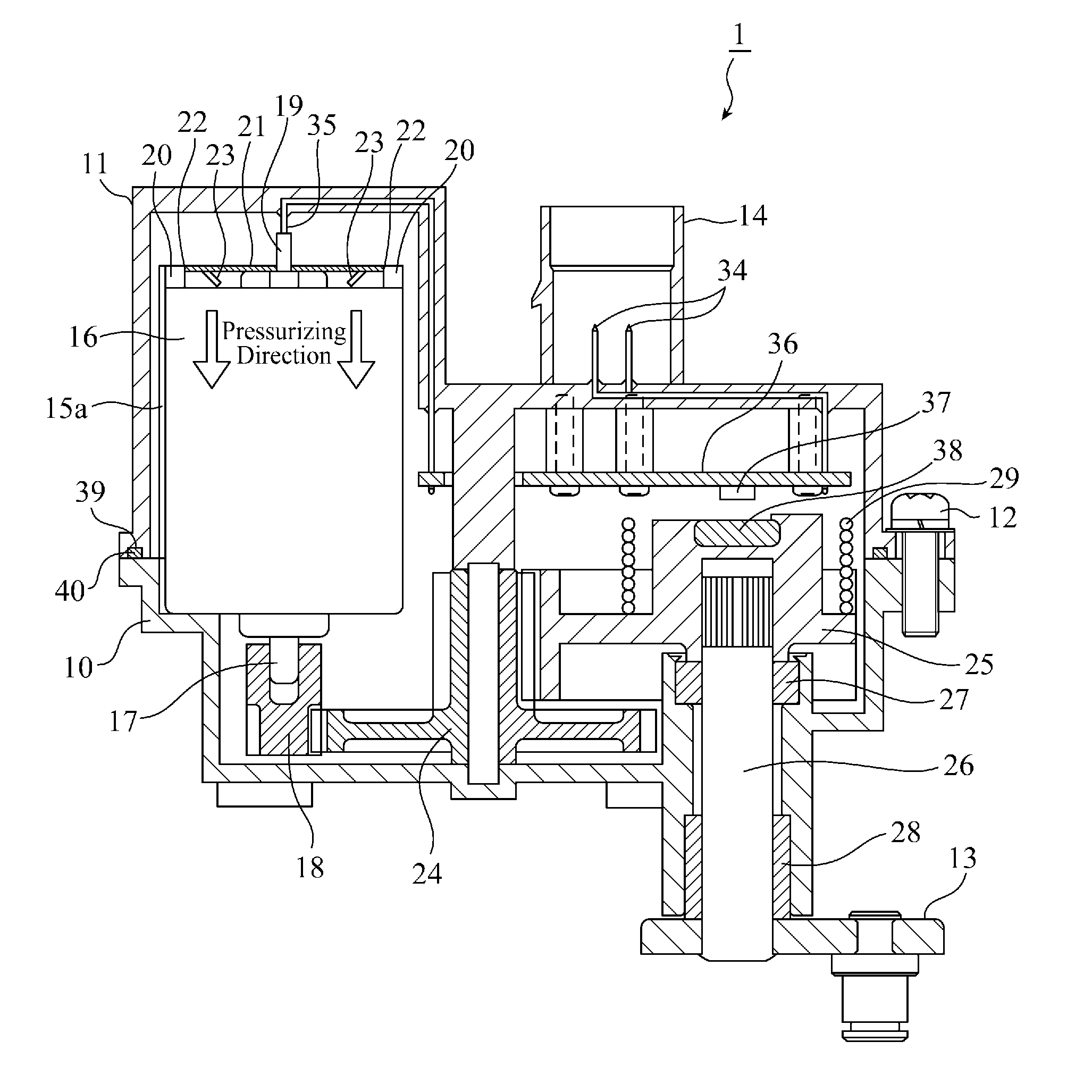
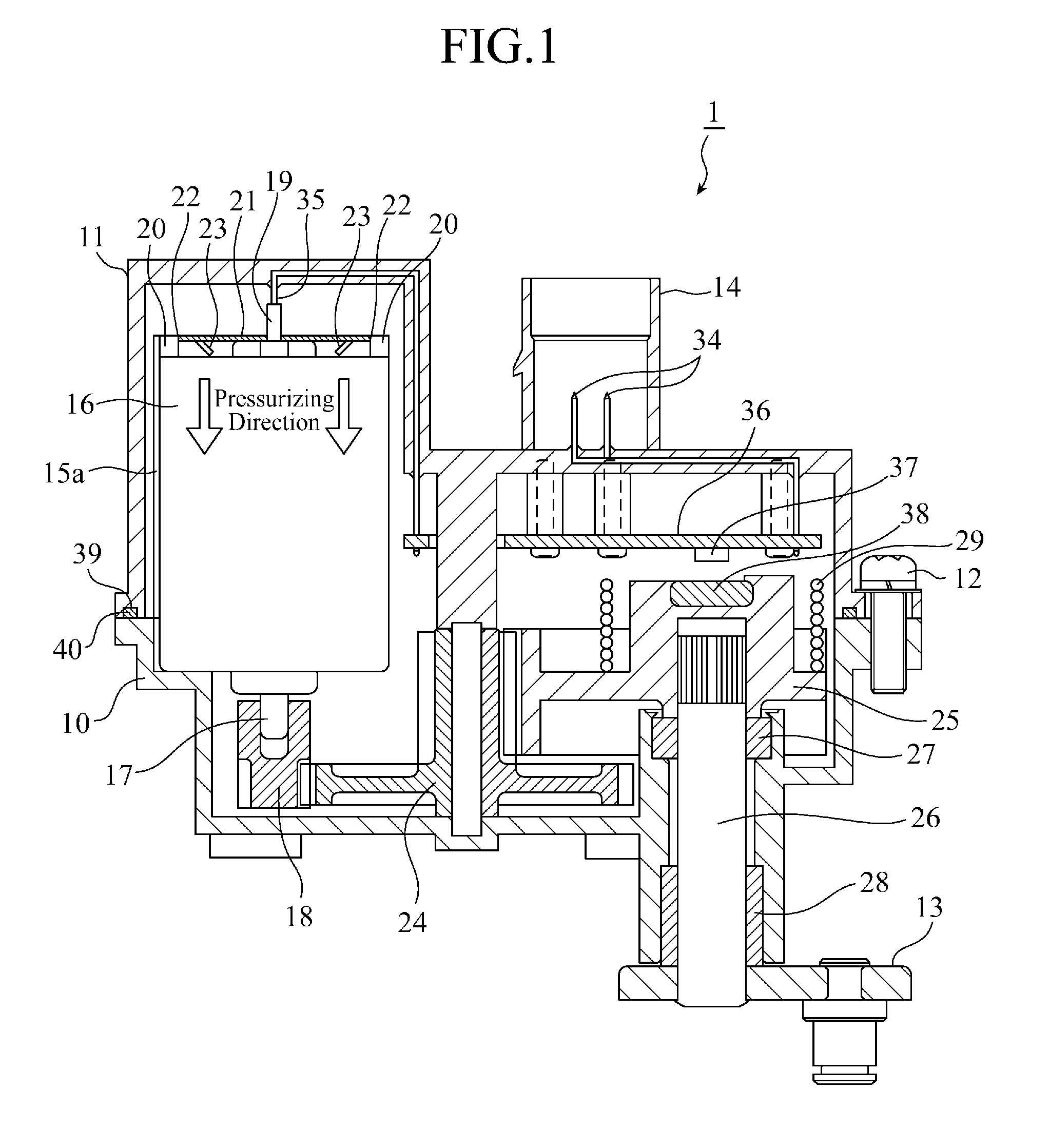
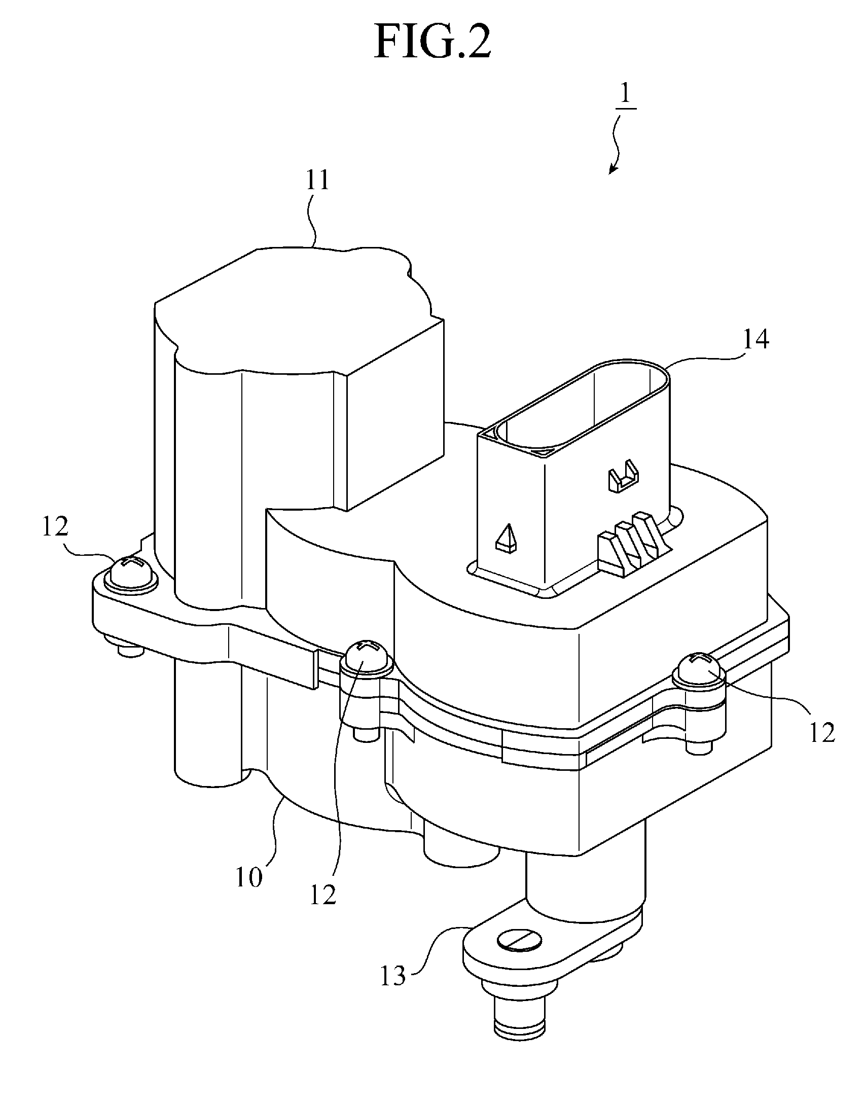
[0021]As shown in FIGS. 1 to 3, an electronically controlled actuator 1 is composed of an actuator housing 10 made of an aluminum alloy and a resin-made cover 11 made of a resin to be fastened with a plurality of screws 12. A lever 13 is provided on the base side of the actuator housing 10 and the lever 13 is connected to nozzle vanes (not shown).

[0022]FIGS. 4 and 5 show states of the electronically controlled actuator 1 from which the cover 11 is removed. As shown in FIGS. 1, 4 and 5, the actuator housing 10 is composed of the base and side peripheral walls, while the top thereof is open. Motor support posts 15, 15 are protrusively provided in the actuator housing 10 toward the open top side, and also motor support faces 15a, 15a are formed on the opposite sides of each of the motor support posts 15, 15. The motor 16 is inserted thereinto, and the motor 16 is supported by the motor support posts 15, 15 and the motor support faces 15a on the opposite sides. A motor shaft 17 projects...


PUM


Abstract

The base of an actuator housing 10 is arranged to face the side of a turbine housing, and a motor 16 is fixed to a motor support post that is protrusively provided toward the top of the actuator housing 10 such that the motor 16 is kept at a distance from the turbine housing.

Description

TECHNICAL FIELD[0001]The present invention relates to an electronically controlled actuator for driving opening and closing of nozzle vanes of a turbo charger.BACKGROUND ART[0002]In a turbo charger in which a turbine is rotated by the exhaust gas from an engine and air is supplied to the engine after being compressed by a compressor arranged on the same axis with the turbine, an electronically controlled actuator drives opening and closing of nozzle vanes mounted on a turbine nozzle to adjust the turbo-charging pressure of the compressor.[0003]FIG. 7 is a cross-sectional view showing the configuration of a conventional electronically controlled actuator 100 arranged around a turbo charger. In the turbo charger, an intake-side compressor housing 2 and an exhaust-side turbine housing 3 are arranged to face each other, while a compressor and turbine housed therein are arranged on the same axis. This axis is arranged within a bearing housing 4 which links the compressor housing 2 and th...

Claims


Application Information

Patent Timeline
Patent Type & Authority Applications(United States)
IPC IPC(8): H02K7/14
CPCF02B37/186Y02T10/144F02B37/24Y02T10/12
Inventor GOTOH, TAKASHI
Owner MITSUBISHI ELECTRIC CORP
Why Eureka
Try Eureka