Segmented/modular magnet bars for sputtering target

a magnet bar and segmental technology, applied in the direction of vacuum evaporation coating, electrolysis components, coatings, etc., can solve the problems of reducing the lifetime of a long magnet bar which extends the length of the target, the distance between the carrier tube and the magnet bar is not uniform, and the fine tuning of the long magnet bar is often difficult. , to achieve the effect of reducing the lifetime of the long magnet bar, facilitating and improving the quality of the sputtering targ

Inactive Publication Date: 2008-02-28
GUARDIAN GLASS LLC +1
View PDF17 Cites 43 Cited by
  • Summary
  • Abstract
  • Description
  • Claims
  • Application Information

AI Technical Summary

Benefits of technology

[0011]In certain example embodiments of this invention, one or more of the magnet segments' height(s) may be adjusted to adjust a magnetic field produced during sputtering. One or more of the magnet segments can be replaced with other magnet segments to vary the modular magnetic bar in certain example embodiments (or the same or different type). Different magnetic fields m...

Problems solved by technology

This adjustment process is sometimes referred to as “tuning.” However, long magnetic bars extending the length of the target may be bent when they are tuned, thus resulting in non-uniform distances with respect to their carrier tubes.
Fine-tuning often is difficult because a large, typically rigid element is being adjusted.
This process also may reduce the lifetime of a long magnet bar which extends the length of the target, which may need to be replaced in its entirety if even part of it...

Method used


Image

  • Segmented/modular magnet bars for sputtering target
  • Segmented/modular magnet bars for sputtering target
  • Segmented/modular magnet bars for sputtering target

Examples


Embodiment Construction

[0021]Referring now more particularly to the accompanying drawings in which like reference numerals indicate like parts throughout the several views.

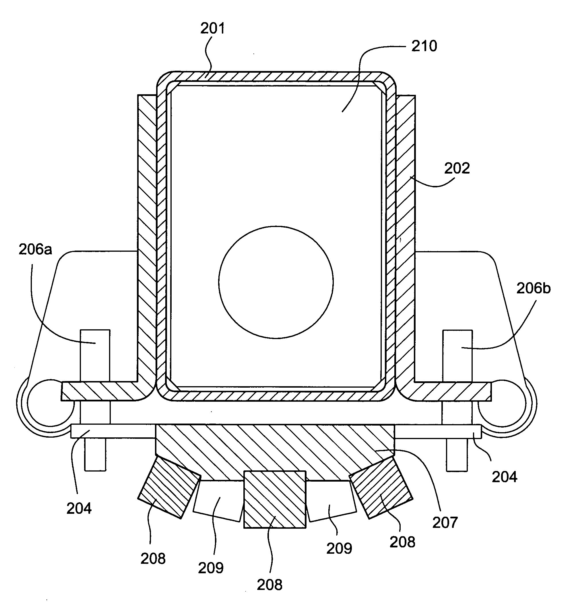
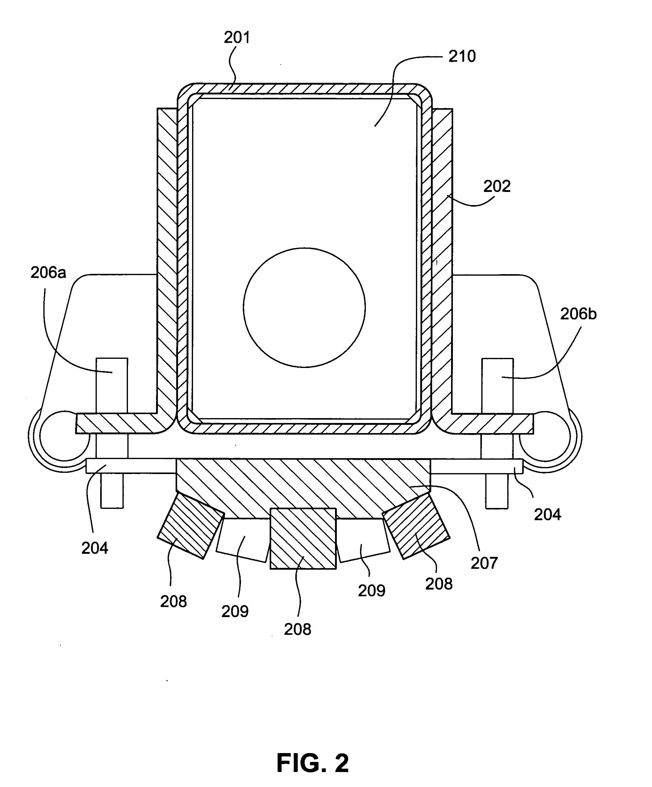
[0022]Certain example embodiments provide a modular and / or segmented magnetic bar structure for sputtering targets. The structure may include a plurality of elongated magnet bars, each magnet bar including a plurality of segments aligned linearly or in series. Such modular magnetic bars may, for example, include five segments (although any suitable number of segments may be provided per bar). Considerations taken into account as to how may segments to provide per magnet bar may include, for example, the size of the sputtering target, the degree of accuracy required with respect to the magnetic field, etc. Multiple segments may be arranged within a sputtering target to function as a single magnet bar. In general, though, more segments in the modular design will allow for more finely-tuned magnetic fields, as each segment preferably can b...


PUM

PropertyMeasurementUnit
Magnetic fieldaaaaaaaaaa
Structureaaaaaaaaaa
Sizeaaaaaaaaaa

Abstract

A modular and/or segmented magnetic bar for magnetron sputtering targets is provided. A magnet bar is made up of a plurality of magnet segments aligned in a substantially linear manner. One or more magnet bars may be provided. The positions of the magnet segments may be selectively adjusted to, for example, adjust magnetic field(s), replace magnet segment(s) that have been broken or damaged, and so forth.

Description

FIELD OF THE INVENTION[0001]This invention relates to rotating sputtering targets, including the use of magnet bars therein, and / or methods of making the same. In certain example embodiments of this invention, a modular and / or segmented magnet bar for a sputtering target is provided, wherein a number of magnet elements may be arranged within a sputtering target to function as a single magnet bar structure. In certain example embodiments, the magnet segments may or may not be of equal lengths. In certain example embodiments, the segments may be tuned and / or replaced to, for example, adjust the magnetic field. Moreover, the segment(s) may also be replaced so as to repair segment(s) that have been broken, damaged, warped, etc.BACKGROUND AND SUMMARY OF EXAMPLE EMBODIMENTS OF THE INVENTION[0002]The use of sputtering in order to deposit coatings on substrates is known in the art. For example, and without limitation, see U.S. Pat. Nos. 5,403,458; 5,317,006; 5,527,439; 5,591,314; 5,262,032;...

Claims


Application Information

Patent Timeline
IPC IPC(8): C23C14/00
CPCC23C14/3407H01J37/3452H01J37/3405C23C14/35
Inventor RICHERT, HENDRYKWEIDL, ROLANDGRUNLER, BERNDJANICKE, GERALDKERN, SIEGFRIEDKRILTZ, UWE
Owner GUARDIAN GLASS LLC
Why Eureka
Try Eureka