Pressure relief valve easy to install

A technology of easy installation and pressure relief valve, applied in the field of pressure relief valve, can solve the problems of inconvenient installation, cumbersome disassembly and assembly steps, and affecting installation efficiency

Active Publication Date: 2021-01-15
山东蓬能机械科技有限公司
View PDF9 Cites 4 Cited by
  • Summary
  • Abstract
  • Description
  • Claims
  • Application Information

AI Technical Summary

Problems solved by technology

[0003] The structure of the existing pressure relief valve is relatively complicated. When the internal parts are damaged or need to be maintained, the valve b

Method used


Image

  • Pressure relief valve easy to install
  • Pressure relief valve easy to install
  • Pressure relief valve easy to install

Examples


Embodiment 1

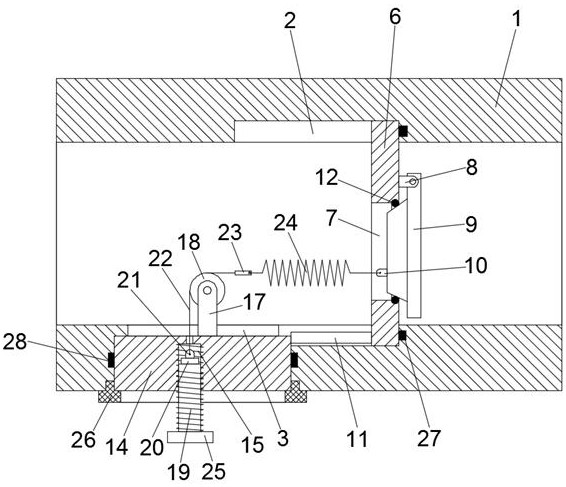
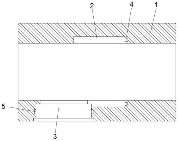
[0029] see Figure 1-2 , a pressure relief valve that is easy to install, including a valve body 1, a partition 6 and a mounting block 14, the inner wall of the valve body 1 is provided with a chute 2, and the partition 6 is slidably clamped in the chute 2, so A stepped mounting hole 3 for accommodating the mounting block 14 is provided on the outer wall of one side of the valve body 1;

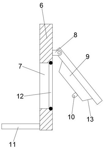
[0030] see image 3 , the partition 6 is provided with a pressure relief port 7, and the end surface of the partition 6 away from the installation hole 3 is provided with a hinged seat 8, and the hinged seat 8 is rotatably connected with a seal for blocking the pressure relief port 7. A cover 9, a first connection seat 10 is installed on the end surface of the cover 9 facing the pressure relief port 7;

[0031] see Figure 4-5 , the mounting block 14 is provided with a threaded hole 15, the bottom of the threaded hole 15 is provided with a through hole 16 communicating with the inside of t...

Embodiment 2

[0044] A pressure relief valve that is easy to install, including a valve body 1, a partition 6 and a mounting block 14, the inner wall of the valve body 1 is provided with a chute 2, and the partition 6 is slidably clamped in the chute 2, the A stepped mounting hole 3 for accommodating the mounting block 14 is opened on the outer wall of one side of the valve body 1;

[0045] The partition 6 is provided with a pressure relief port 7, and the end surface of the partition 6 away from the installation hole 3 is provided with a hinged seat 8, and the hinged seat 8 is rotatably connected with a cover for blocking the pressure relief port 7 9. A first connection seat 10 is installed on the end surface of the cover 9 facing the pressure relief port 7;

[0046] The mounting block 14 is provided with a threaded hole 15, the bottom of the threaded hole 15 is provided with a through hole 16 communicating with the inside of the valve body 1, and the end surface of the mounting block 14 f...


PUM


Abstract

The invention discloses a pressure relief valve easy to install. The pressure relief valve comprises a valve body, a partition plate and a mounting block, and a sliding groove is formed in the inner wall of the valve body; the partition plate is clamped in the sliding groove slidably, and a stepped mounting hole is formed in one side of the valve body; a pressure relief opening is formed in the partition plate, and the end face of one side of the partition plate is rotatably connected with a sealing cover; a threaded hole is formed in the mounting block, and a guide wheel is rotatably mountedon the end face facing the interior of the valve body; a locking snap ring is mounted between the mounting block and the mounting hole; a stud is arranged in the threaded hole in a threaded sleeving mode, a stay rope is connected with the stud; and the stay rope is rotatably wound around the guide wheel, and a spring is connected between the tail end of the stay rope and the sealing cover. The pressure relief valve east to install is simple in structure, and the sliding groove and the mounting hole are formed in the valve body, so that rapid disassembly and assembly of the partition plate andthe mounting block are achieved; internal components can be replaced, maintained and cleaned without disassembly of the whole valve body, and the disassembly and assembly time is saved; and the stud is rotated to drive the spring to stretch for adjustment, so that the pressure relief threshold is changed, and the adjustment is convenient and efficient.

Description

technical field [0001] The invention relates to the technical field of pressure relief valves, in particular to a pressure relief valve which is easy to install. Background technique [0002] The pressure relief valve, also known as the safety valve, can automatically open and close according to the working pressure of the system. It is generally installed on the equipment or pipeline of the closed system to protect the safety of the system. When the pressure in the equipment or pipeline exceeds the set pressure of the pressure relief valve, it will automatically open the pressure relief to ensure that the medium pressure in the equipment and pipeline is below the set pressure, protect the equipment and pipeline, and prevent accidents. [0003] The structure of the existing pressure relief valve is relatively complicated. When the internal parts are damaged or need to be maintained, the valve body must be dismantled as a whole, and then the internal parts are taken out one b...

Claims


Application Information

Patent Timeline
IPC IPC(8): F16K17/06F16K27/02
CPCF16K17/0413F16K17/06F16K27/0227
Inventor 刘钟泉张伟红
Owner 山东蓬能机械科技有限公司
Why Eureka
Try Eureka