Pedal effort adjusting apparatus of accelerator pedal

a technology of pedal effort and adjustment apparatus, which is applied in the direction of mechanical control devices, process and machine control, instruments, etc., can solve the problems of inability to efficiently sense the feeling of accelerator pedal manipulation, inability to adjust the pedal effort, and widespread use, so as to efficiently meet the effect of adjusting the pedal effor

Active Publication Date: 2015-09-22
HYUNDAI MOTOR CO LTD
View PDF15 Cites 4 Cited by
  • Summary
  • Abstract
  • Description
  • Claims
  • Application Information

AI Technical Summary

Benefits of technology

[0010]Accordingly, the present invention has been made keeping in mind the above problems occurring in the related art, and various aspects of the present invention are intended to propose a pedal effort adjusting apparatus of an accelerator pedal, which can efficiently adjust the pedal effort of the assembled accelerator pedal when necessary, and so the apparatus can efficiently meet the safety laws and regulations relating to pedal efforts in a country, and can realize the ubiquitous use of the accelerator pedal.
[0018]The pedal effort adjusting apparatus of the accelerator pedal according to the present invention is advantageous in that the elasticity of the elastic member can be easily adjusted by changing the length of the elastic member according to a simple rotation of the movable plate, thereby easily and efficiently adjusting the accelerator pedal effort as desired, and in that the pedal effort adjusting apparatus can be commonly used with various types of accelerator pedals.

Problems solved by technology

However, the conventional accelerator pedal is problematic in that, when the pedal effort is too high, a driver is required to apply a high level of force to the pedal arm 2, and so the driver may easily feel fatigue from repeated manipulation of the accelerator pedal, and when the pedal effort is too low, the driver may not efficiently sense the feeling of accelerator pedal manipulation.
However, the conventional accelerator pedal that has been completely assembled with fixed pedal effort characteristics is problematic in that it is impossible to adjust the pedal effort, and so the accelerator pedal having the fixed pedal effort characteristics may not be used ubiquitously.

Method used


Image

  • Pedal effort adjusting apparatus of accelerator pedal
  • Pedal effort adjusting apparatus of accelerator pedal
  • Pedal effort adjusting apparatus of accelerator pedal

Examples


Embodiment Construction

[0022]Reference will now be made in detail to various embodiments of the present invention(s), examples of which are illustrated in the accompanying drawings and described below. While the invention(s) will be described in conjunction with exemplary embodiments, it will be understood that present description is not intended to limit the invention(s) to those exemplary embodiments. On the contrary, the invention(s) is / are intended to cover not only the exemplary embodiments, but also various alternatives, modifications, equivalents and other embodiments, which may be included within the spirit and scope of the invention as defined by the appended claims.

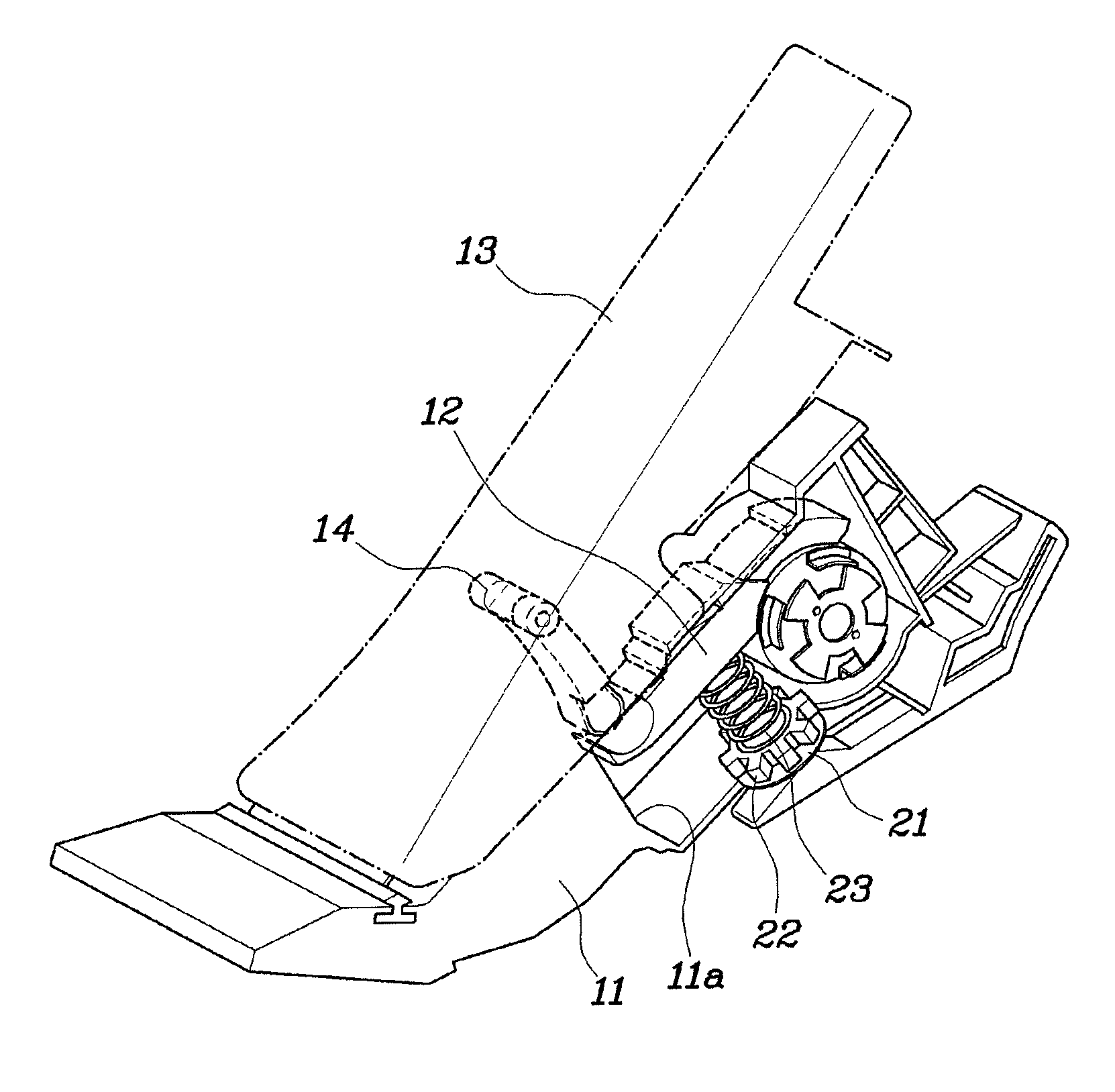
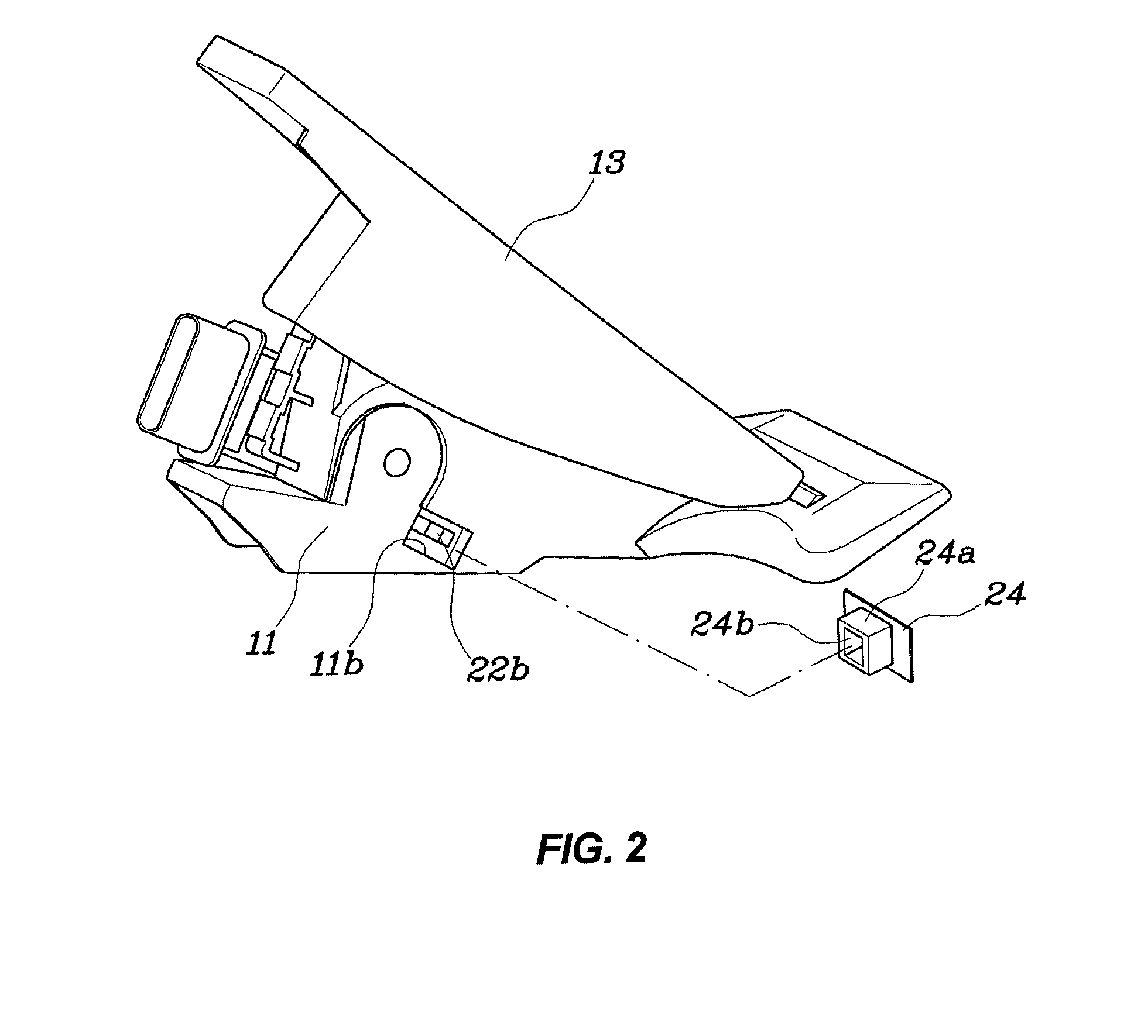
[0023]FIGS. 2 and 3 illustrate the construction of an organ type accelerator pedal that is an example of accelerator pedals of vehicles. As shown in FIGS. 2 and 3, the accelerator pedal comprises: a pedal arm housing 11 that is fixedly mounted to a body panel placed below a driver's seat, and has an inner space 11a; a pedal arm 12 tha...


PUM


Abstract

An accelerator pedal effort adjusting apparatus can easily adjust the elasticity of an elastic member by changing the length of the elastic member according to a simple rotation of a movable plate, thereby easily adjusting the accelerator pedal effort as desired. The apparatus can be commonly used with various types of accelerator pedals. The apparatus includes: a guide rod installed such that it is mounted to the bottom surface of the inner space of a pedal arm housing and is directed toward a pedal aim; a movable plate movably fitted over the guide rod such that the movable plate can be moved along the guide rod; and an elastic member installed in such a way that the elastic member is supported by both the pedal arm and the movable plate at opposite ends thereof, and applies a reaction force to a pedal pad.

Description

CROSS-REFERENCE TO RELATED APPLICATION[0001]The present application claims priority of Korean Patent Application Number 10-2013-0072561 filed Jun. 24, 2013, the entire contents of which application is incorporated herein for all purposes by this reference.BACKGROUND OF INVENTION[0002]1. Field of Invention[0003]The present invention relates, in general, to a pedal effort adjusting apparatus of an accelerator pedal, which can adjust the pedal effort of an accelerator pedal in response to a simple manipulation of a user.[0004]2. Description of Related Art[0005]FIG. 1 illustrates an example of conventional accelerator pedals of vehicles. As shown in FIG. 1, the conventional accelerator pedal includes: a pedal housing 1 that is fixedly mounted to a body panel placed below a driver's seat; a pedal arm 2, a first end of which is provided with a pedal pad 2a, and a second end of which is inserted into the pedal arm housing 1 and is mounted such that the pedal arm 2 can be rotated relative t...

Claims


Application Information

Patent Timeline
Patent Type & Authority Patents(United States)
IPC IPC(8): G05G1/30G05G1/40
CPCG05G1/40Y10T74/20534G05G1/44G05G5/05G05G1/30B60K26/02
Inventor KIM, EUN SIK
Owner HYUNDAI MOTOR CO LTD
Why Eureka
Try Eureka