

Body canal dilation system
a body canal and dilation system technology, applied in the direction of dilation devices, catheters, surgery, etc., can solve the problems of not being able to prevent the dilating rod from being inserted into the uterine cavity, the person performing the dilation procedure cannot control the insertion of the metal rod, and the rod may be accidentally inserted farther than desired, so as to reduce the risk of uterine perforation, cervical laceration and soft tissue injury, and more user control
- Summary
- Abstract
- Description
- Claims
- Application Information
AI Technical Summary
Benefits of technology
Problems solved by technology
Method used
Image

Examples
Embodiment Construction
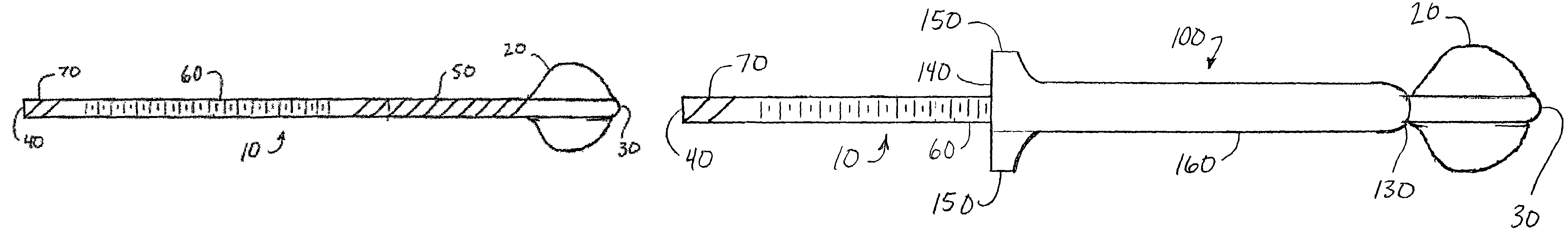
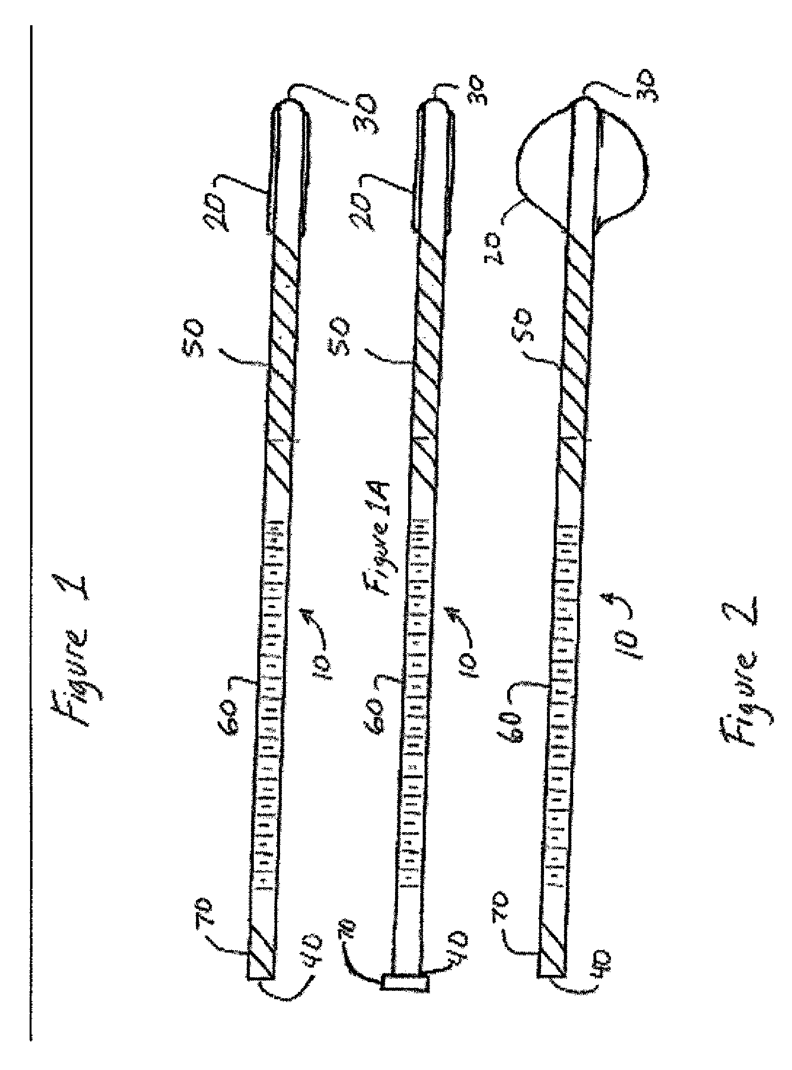
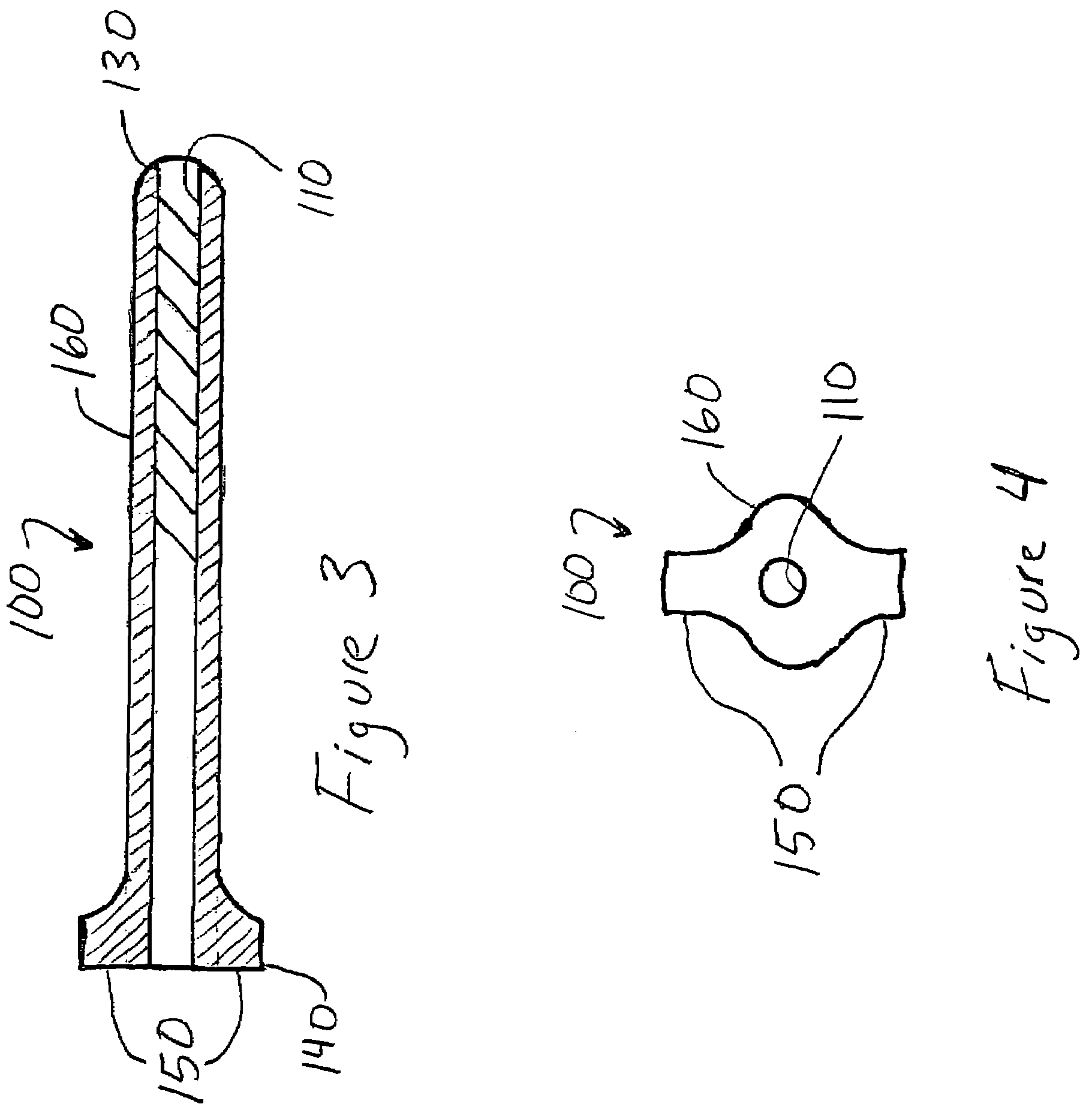
[0009]Preferred embodiments of the present invention are disclosed as having a cylindrical rod with an inflatable member at one end and a tubular member capable of threaded engagement with the cylindrical rod. Preferred embodiments control the insertion of the tubular member by threaded engagement between the tubular member and cylindrical rod. Preferred embodiments also utilize the inflatable member to prevent the tubular member from being inserted past a desired point. Preferred embodiments also comprise graduated markings on the cylindrical rod to allow the person performing the procedure to know how far the cylindrical rod or tubular member has been inserted.
[0010]Thus, the embodiments of the cervical dilation system summarized above comprise a combination of various features and advantages that enable the system to overcome various problems of prior devices. Preferred embodiments of the present invention will allow more user control while also decreasing the risk of uterine per...
PUM
 Abstract
Description
Claims
Application Information