Bed pad

Inactive Publication Date: 2005-03-17
ILLINOIS TOOL WORKS INC
View PDF31 Cites 51 Cited by
  • Summary
  • Abstract
  • Description
  • Claims
  • Application Information

AI Technical Summary

Benefits of technology

[0007] It is also desirable to provide an improved lightweight, po

Problems solved by technology

However, several problems may be encountered in the movement of a patient.
Problems are also encountered when it is necessary to either adjust the patient's position in the bed or transfer them to another bed.
The patient is potentially subjected to numerous movements, each with the

Method used


Image

  • Bed pad
  • Bed pad
  • Bed pad

Examples


Embodiment Construction

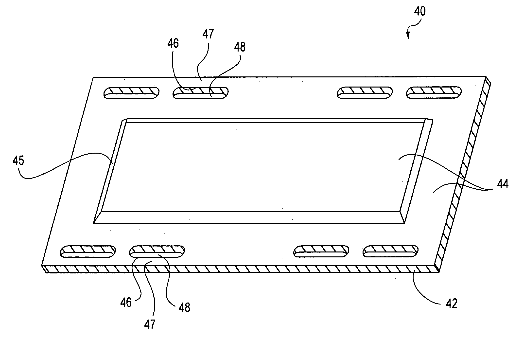
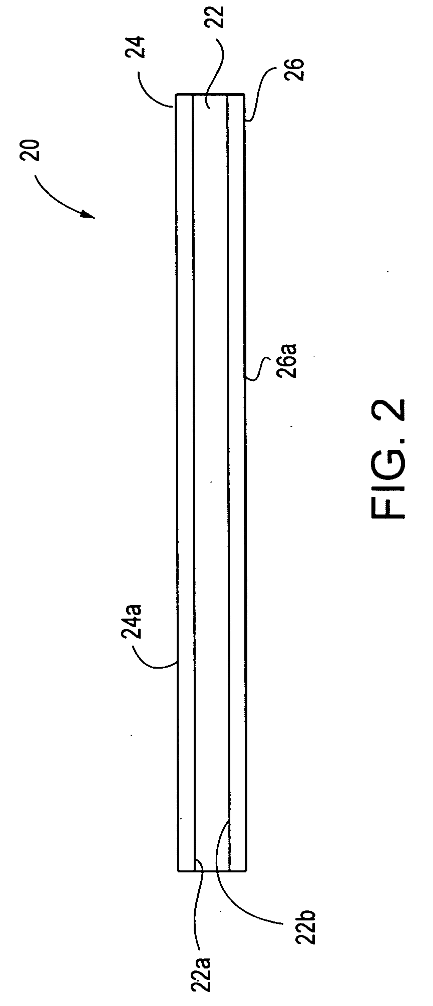
[0025] A bed pad is provided that comprises at least two layers and is capable of being used as an aid for the easy adjustment of patients within a bed and / or the easy transfer of a patient from one bed to another bed or medical table. It can also be used as the flexible fabric material between the two poles of a stretcher or, carried separately, as a bedroll. The present invention bed pad can serve multiple applications. A bed pad according to the present invention comprises a padding layer and at least one sheet layer adjacent to the padding layer. The padding layer is comprised of a pad or mat and provides support for the bed pad of the invention. The sheet layer is a layer adjacent to the padding layer, and provides the surface upon which the patient lies. Other layers may be included depending upon the end use application.

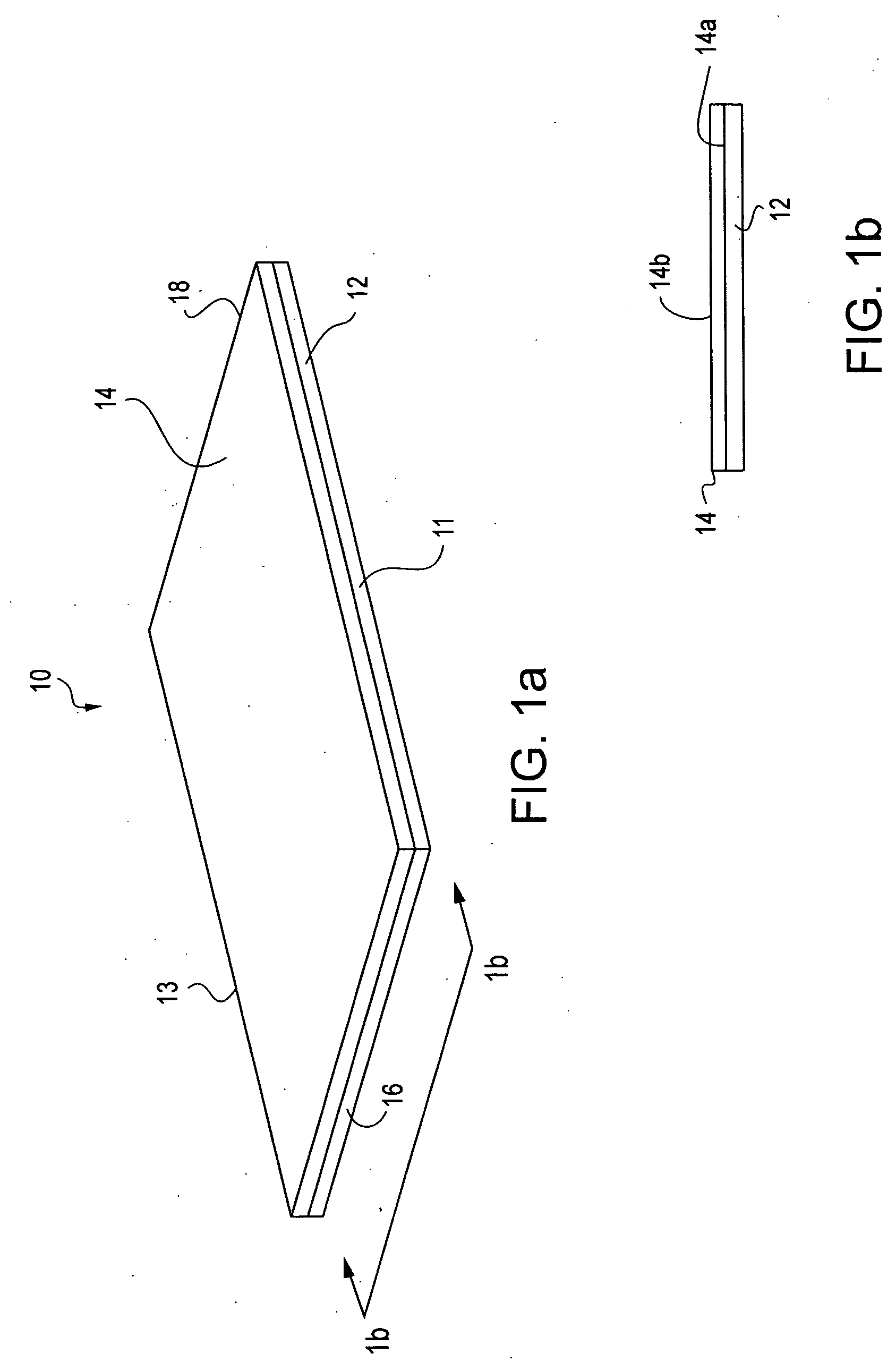
[0026] In a first configuration, such as the embodiment shown in FIGS. 1a and 1b, a bed pad 10 according to the invention is a two-layer or laminate construc...


PUM


Abstract

A bed pad is disclosed comprising a padding layer and at least one sheet layer adjacent to the padding layer. The padding layer provides support for the patient. The sheet layer comprises a fabric material that is comfortable for the patient to use. The bed pad provides a means for either adjusting a patient within a bed or for transferring a patient from one bed to another bed or medical table. The bed pad may also be used as part of a stretcher or separately as a bedroll. The bed pad may optionally contain gripping components and drapes.

Description

CROSS REFERENCES TO RELATED APPLICATIONS [0001] This application claims the benefit of U.S. provisional patent application Ser. No. 60 / 502,779, filed Sep. 12, 2003.BACKGROUND OF THE INVENTION [0002] For a variety of reasons and situations, patients in a hospital or medical environment frequently need to be moved. A patient may need to be moved to reposition the patient within their bed, transfer the patient from one bed to another bed or medical table, or to change the patient's bedding. However, several problems may be encountered in the movement of a patient. Physically lifting the patient may require several medical staff members to lift the patient to ensure that the patient's limbs and / or extremities are not loose and subject to jostling or random motions that may cause discomfort. Even if several persons assist in the lifting of the patient, the patient may be subjected to subtle movements in direction if the persons moving the patient do not act in concert with one another. P...

Claims


Application Information

Patent Timeline
IPC IPC(8): A61G1/01A61G7/10
CPCA61G1/01A61G2200/32A61G7/103
Inventor ASSINK, KENNETH
Owner ILLINOIS TOOL WORKS INC
Why Eureka
Try Eureka