Tension feedback system for a tape drive

a tape drive and feedback system technology, applied in the direction of maintaining head carrier alignment, mechanical tension control of the carrier, instruments, etc., can solve the problem of unacceptable stress levels in the edges of the tape medium

Inactive Publication Date: 2005-03-17
QUANTUM CORP
View PDF10 Cites 7 Cited by
  • Summary
  • Abstract
  • Description
  • Claims
  • Application Information

AI Technical Summary

Problems solved by technology

Tension variation within the tape path may produce spikes in the lateral tape motion (LTM) and can cause unacceptable levels of stress in the edges of the tape medium 110.

Method used


Image

  • Tension feedback system for a tape drive
  • Tension feedback system for a tape drive
  • Tension feedback system for a tape drive

Examples


Embodiment Construction

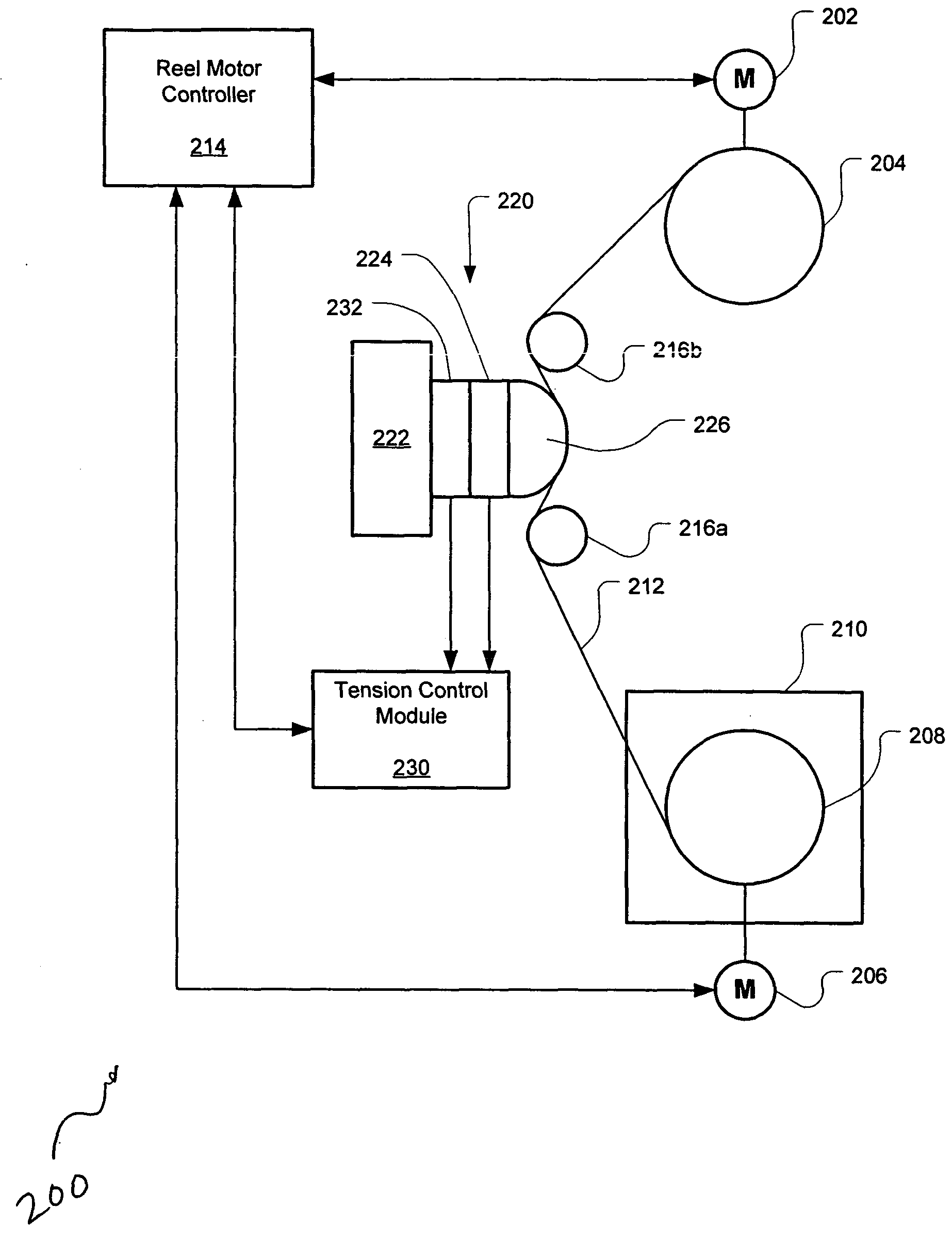
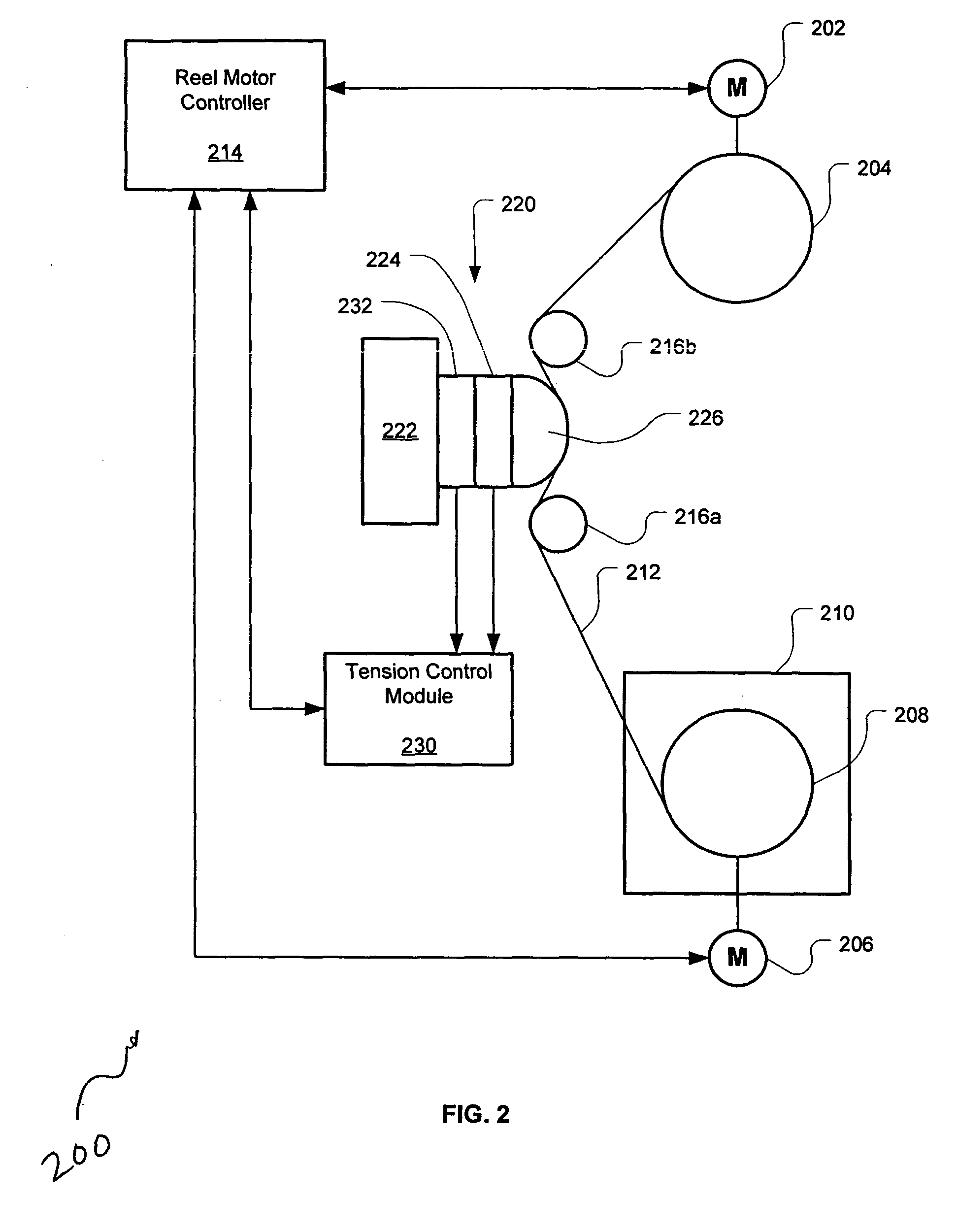
[0014]FIG. 2 is a simplified block diagram showing a tape drive system 200 in accordance with embodiments of the present invention. The tape drive system 200 comprises a take-up reel motor 202 coupled to a take-up reel 204, and a supply reel motor 206 coupled to a supply reel 208. The supply reel 208 is provided within a tape cartridge 210 and has a length of tape medium 212 wrapped around it. When the tape cartridge 210 is loaded into the tape drive system 200, the tape medium 212 is coupled with the take-up leader and then is wrapped around the take-up reel 204. The path that the tape medium 212 travels as it passes from the supply reel 208 to the take-up reel 204 is the tape path. The take-up reel motor 202 and the supply reel motor 206 are controlled by the reel motor controller 214 to rotate the take-up reel 204 and the supply reel 208, respectively, in order to move the tape medium 212 back and forth between the two reels 204, 208.

[0015] The tape drive system 200 further comp...


PUM

PropertyMeasurementUnit
pressureaaaaaaaaaa
accelerationaaaaaaaaaa
tensionaaaaaaaaaa

Abstract

Tape drive systems and methods for operating tape drive systems are provided. The system includes a head assembly having a head element for reading or writing data to a magnetic tape medium, and a pressure sensor coupled to the head element, the pressure sensor configured to generate a pressure signal representative of a pressure applied by the head element onto the pressure sensor. In some embodiments, an accelerometer is provided for sensing an acceleration of the head assembly and for generating a acceleration signal representative of an acceleration experienced by the head assembly. The method includes passing a tape medium between a take-up reel and a supply reel such that a tension in the tape medium causes the tape medium to apply a pressure onto a head element, and using a pressure sensor to detect a pressure applied by the head element onto the pressure sensor.

Description

BACKGROUND OF THE INVENTION [0001] Storage subsystems, such as magnetic tape libraries, are widely used for storing information in digital form. Tape storage subsystems typically include one or more tape drives for reading and writing data to removable tape cartridges. FIG. 1 shows a simplified view of an exemplary tape drive 100 having a removable tape cartridge 106 loaded therein. The tape cartridge 106 typically comprises a cartridge housing enclosing a tape medium 110 wound about a rotatable supply reel 108. The tape drive 100 typically includes a take-up reel 101, a plurality of rollers 102, and a read / write head 104. The take-up reel 101 includes a take-up leader that is coupled to a supply leader extending from one end of the tape medium 110, when the tape cartridge 106 is loaded into the tape drive 100. The tape medium 110 typically comprises a thin film of magnetic material which stores the data. To read or write data, the tape medium 110 is spooled between the take-up reel...

Claims


Application Information

Patent Timeline
Patent Type & Authority Applications(United States)
IPC IPC(8): G11B15/43
CPCG11B15/43
Inventor EGAN, BRIAN
Owner QUANTUM CORP
Why Eureka
Try Eureka