Eureka AIR delivers breakthrough ideas for toughest innovation challenges, trusted by R&D personnel around the world.

Tape head module assembly system

Inactive Publication Date: 2005-03-17
IBM CORP
View PDF18 Cites 2 Cited by
  • Summary
  • Abstract
  • Description
  • Claims
  • Application Information

AI Technical Summary

Benefits of technology

[0034] In another embodiment of the present invention, a tape head module assembly method is provided. The method includes placing a first and second module holder in an initial state with module holder ends facing each other, the module ends each holding a tape head module, setting a tape wrap angle between the first and second module by performing initial alignment, lifting a rear end of the first and second module holder a prescribed amount, selecting a horizontal alignment for the first module holder so that

Problems solved by technology

However, the development of small footprint, higher performance tape drive systems has created various problems in the design of a tape head assembly for use in such systems.
However, the two tape head sections may shift relative to one another during this joining process.
Previous two module tape head build methods do not have generally the required level of precision for modern high density recording applications.
However, in general it is very difficult to hold, align and join the two modules to one another.
Moreover, the alignment precision required makes the task even more difficult, if not impossible.
Cylindrical contoured heads rely on datum unit alignment for setting the wrap angle, and this is generally not applicable to flat contoured heads.
In addition spring loaded pin tooling used for cylindrically contoured heads does not meet the increasing demands of tighter track-to-track and other alignments required by narrow track width heads because such designs are plagued by stiction and erratic setup performance, and furthermore do not provide means for gripping the modules for accurate alignment independent of other tolerances.

Method used


Image

  • Tape head module assembly system
  • Tape head module assembly system
  • Tape head module assembly system

Examples


Embodiment Construction

[0057] In the following description of the exemplary embodiment, reference is made to the accompanying drawings that form a part hereof, and in which is shown by way of illustration the specific embodiment in which the invention may be practiced. It is to be understood that other embodiments may be utilized as structural changes may be made without departing from the scope of the present invention.

[0058] The present invention provides a tape head module assembly system and method that systematizes tape head alignment and provides micron level alignment tolerances.

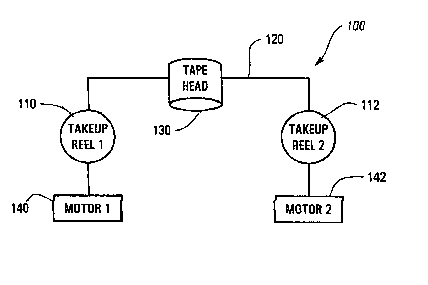
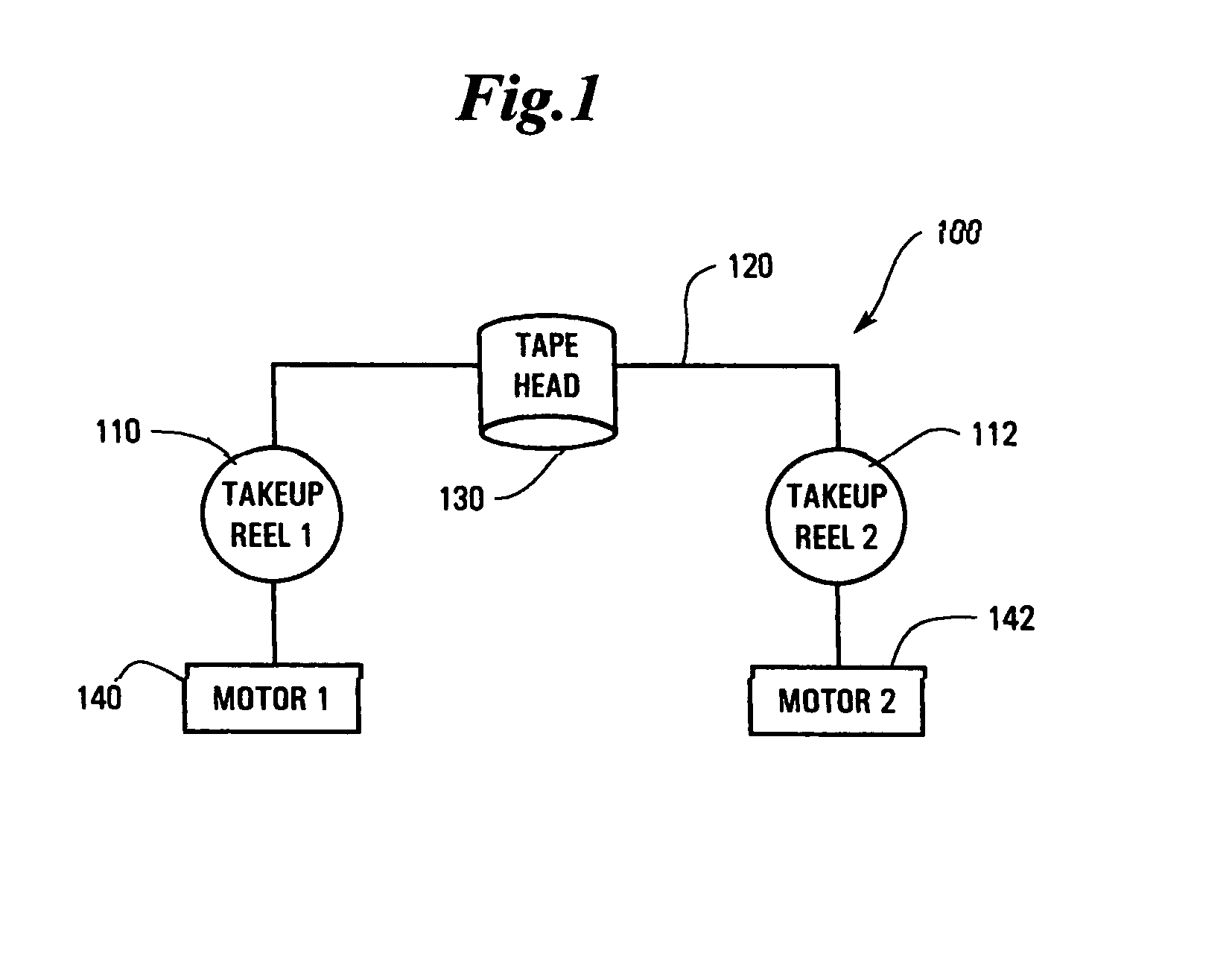
[0059]FIG. 1 illustrates a tape system 100 according to the present invention. The tape system 100 includes a first supply and a second take-up reel 110, 112. Magnetic recording tape 120 is spooled on the first and second take-up reels 110, 112. The magnetic recording tape 120 is routed over a tape read / write head 130 for reading and writing data on the magnetic recording tape 120. Take-up reel motors 140, 142 control the...


PUM

PropertyMeasurementUnit
Transparencyaaaaaaaaaa
Surface areaaaaaaaaaaa

Abstract

A tape head module assembly system is disclosed. A first and second module holder are placed in an initial alignment with module holder ends facing each other, the module ends each holding a tape head module. A tape wrap angle between the first and second module is set by first performing a fringe alignment and then lifting a rear end of the first and second module holder a prescribed amount. A horizontal adjuster produces a rotation for the first module holder so that gaps between the first and second modules are parallel. An alignment along a longitudinal axis for the second module holder is selected and the second module is translated laterally until the second tape head module held by the second module holder is aligned with the first tape head module held by the first module holder to provide reader-opposite-writer track-to-track registration. Then, the first and second tape head modules are joined together using a joining agent in the gap between the first and second tape head modules.

Description

RELATED PATENT DOCUMENTS [0001] This application is a divisional of U.S. patent application Ser. No. 09 / 938,187, filed on Aug. 23, 2001, to which priority is claimed under 35 U.S.C. § 120, and which is incorporated herein by reference.BACKGROUND OF THE INVENTION [0002] 1. Field of the Invention. [0003] This invention relates in general to tape head assemblies, and more particularly to a tape head module assembly system and method. [0004] 2. Description of Related Art. [0005] In high-speed data processing systems, magnetic recording has been employed for large storage capacity requirements. In magnetic storage systems, data is read from and written onto magnetic recording media utilizing magnetic transducers commonly referred to as magnetic heads. Data is written on the magnetic material by moving a magnetic recording head to a position over the magnetic material where the data is to be stored. The magnetic recording head then generates a magnetic field, which encodes the data into t...

Claims


Application Information

Patent Timeline
IPC IPC(8): G11B5/56
CPCG11B5/56Y10T29/49032Y10T29/53165Y10T29/53196Y10T29/49028Y10T29/4905Y10T29/49021Y10T29/49902Y10T29/49901Y10T29/5313Y10T29/51
Inventor BISKEBORN, ROBERT GLENN
Owner IBM CORP
Why Eureka
Eureka Blog
Learn More