Multi-linking, rear suspension system for two-wheeled motor vehicles

a rear suspension and motorcycle technology, applied in the field of two-wheeled vehicles, can solve the problems of lateral instability of the rear wheel of the motorcycle, insufficient control of the wheel to the pavement contact, and compromised system efficiency and stability, and achieve the effect of lateral stability

Inactive Publication Date: 2005-03-31
MAYFRAN +1
View PDF16 Cites 3 Cited by
  • Summary
  • Abstract
  • Description
  • Claims
  • Application Information

AI Technical Summary

Benefits of technology

[0013] The above-described system has a generally triangular configuration. With the system of the present invention, lateral stability is created for the rear wheel of the two-wheeled vehicle. In addition the axle location for the wheel is controlled in a structured motion in relation to the drive system, sprocket or shaft. The length of the arm assemblies and the length of the pivot arm assemblies interconnected with the control arms achieve the ability to position the rear axle in a unlimited number of positions in relation to the frame. This also means that it has the ability for a maintained equal distance from the drive system, sprocket or shaft in relation to the rear axle location in motion thus allowing no slack to be created in the drive system.

Problems solved by technology

In this respect, when the shock system is affected by power or braking to the rear wheel, system efficiency and stability are compromised.
Although recent motorcycle frames include a swing arm configuration, these configurations posses certain deficiencies that detract from their overall utility.
This causes lateral instability for the rear wheel of the motorcycle.
Many existing suspension systems provide inadequate control of the wheel to pavement contact.
This can create safety concerns regarding the control of the increased stopping during braking.

Method used


Image

  • Multi-linking, rear suspension system for two-wheeled motor vehicles
  • Multi-linking, rear suspension system for two-wheeled motor vehicles
  • Multi-linking, rear suspension system for two-wheeled motor vehicles

Examples


Embodiment Construction

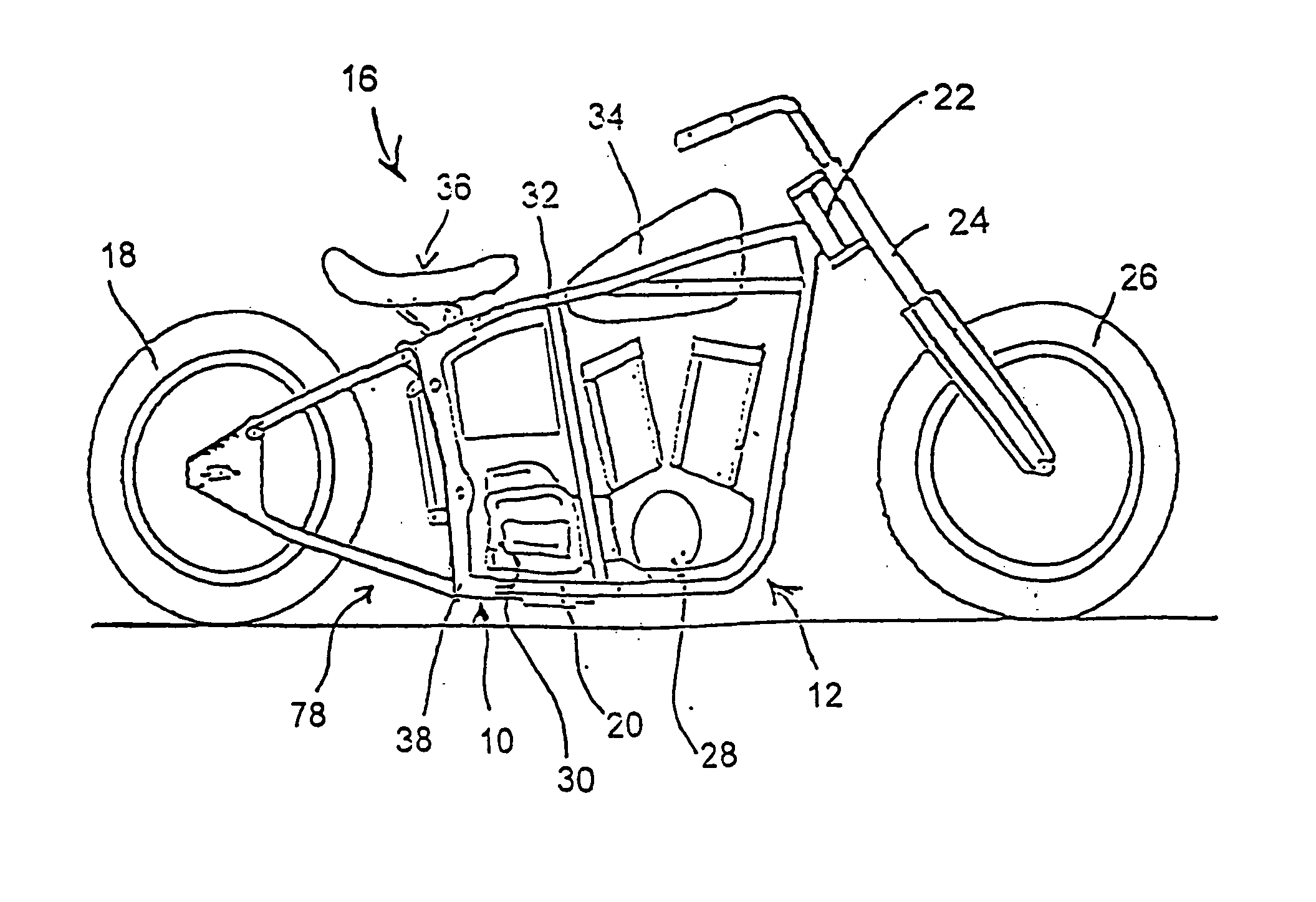
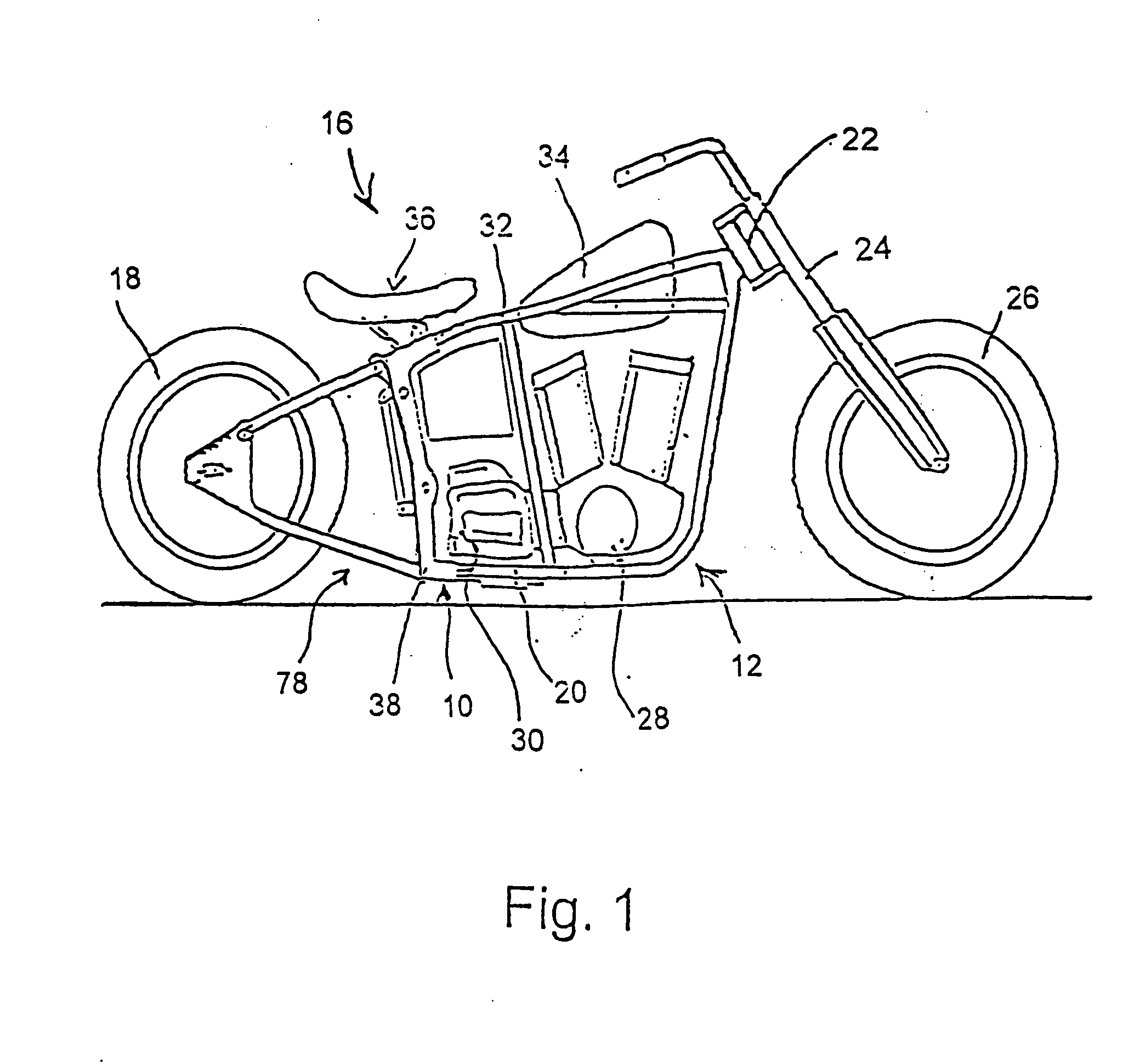
[0023] As shown in the drawings for purposes of illustration, the present invention is concerned with a rear suspension system for two-wheeled vehicles, generally referred to by the reference number 10 in FIGS. 1-6. The rear suspension system 10 is particularly designed and adapted for use in a motorcycle 16, although it could conceivably be incorporated into any two-wheeled vehicle.

[0024] With reference to FIG. 1, a motorcycle 16 is illustrated incorporating the rear suspension system 10 of the present invention. The primary structural component of the motorcycle is the frame 12. The frame 12 is typically comprised of two bottom support tubes 20 which are bent at an upwardly directed angle at a front end thereof to a head tube 22. The head tube 22 is connected to a front wheel torque assembly 24 upon which the front wheel 26 is rotatably mounted. The bottom support tubes 20 also provide an anchor and base for the motor 28, transmission 30, etc. A top support tube 32 extends from t...


PUM


Abstract

A rear suspension system for two-wheeled motor vehicles having a generally triangular configuration includes upper and lower pivot arm assemblies pivotally connected to a frame of the vehicle. A control arm is interconnected between the pivot arm assemblies. A rear wheel supporting unit, including upper and lower arm assemblies, is connectable to an axle of a rear wheel of the vehicle at a first end thereof. The upper arm assembly of the supporting unit is connected to the upper pivot arm assembly. The lower arm assembly of the supporting unit is connected to the lower pivot arm assembly. A compressible shock unit is provided to dampen movement of the system.

Description

RELATED APPLICATION [0001] This application is a continuation application of U.S. application Ser. No. 10 / 414,631, filed Apr. 15, 2003, which is a continuation-in-part application of U.S. application Ser. No. 10 / 050,315, filed Jan. 15, 2002, which is a continuation-in-part application of U.S. application Ser. No. 09 / 740,517, filed Dec. 19, 2000.BACKGROUND OF THE INVENTION [0002] The present invention relates generally to two-wheeled vehicles. More particularly, the present invention relates to a rear suspension system for two-wheeled motor vehicles, such as motorcycles, employing pivoting arm assemblies and control arms possessing shock absorption characteristics and providing lateral stability. [0003] The existing designs of most prior art rear suspension assemblies for two-wheeled motor vehicles include a rear pivot from a single point either from a dual or mono shock system that either extends or comprises the shock unit. In this respect, when the shock system is affected by powe...

Claims


Application Information

Patent Timeline
Patent Type & Authority Applications(United States)
IPC IPC(8): B62K25/28
CPCB62K25/286B62K25/283
Inventor PARIGIAN, GREG M.
Owner MAYFRAN
Why Eureka
Try Eureka