A suspension-arch composite system bridge

A technology for bridges and cantilevered arches, applied in the field of suspended arch composite bridges, can solve the problems of quality limitation, rope tensile elastic bridge rigidity, etc., and achieve the effect of reducing burden and requirements, improving rigidity and increasing bearing capacity

Active Publication Date: 2019-04-09
张圳霖
View PDF5 Cites 0 Cited by
  • Summary
  • Abstract
  • Description
  • Claims
  • Application Information

AI Technical Summary

Problems solved by technology

It solves the problem that the span of the rope bridge is limited by the quality of the load-bearing rope in the prior art, and the problem that the length of the arch rod is limited by the bending force of gravity within the bridge span range and the traditional arch rod's self-seismic and anti-bending ability under the action of force problems, and the wind resistance problem caused by the tensile elasticity of the rope, that is, the rigidity of the bridge, and the stability of the arch

Method used


Image

  • A suspension-arch composite system bridge
  • A suspension-arch composite system bridge
  • A suspension-arch composite system bridge

Examples


Embodiment 1

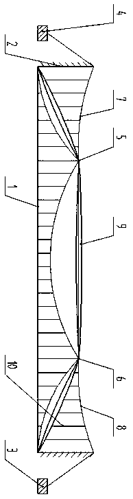
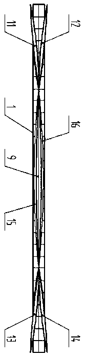
[0034] As shown in the accompanying drawings of the description, a bridge with a suspension arch combination system includes a bridge span 1, a cable tower 2, an anchor 2 3, an anchor 4, a support beam 17, a fastening beam frame 18, a cable hole 19, a bearing Point 2 5, Supporting point 1 6, supporting arch suspension cable 1 7, supporting arch suspension cable 2 8, horizontal arch rod 9, ballistic structure sling 10, inclined arch rod 1 A 11, inclined arch rod 1 B 12, oblique arch rod 1 Arch pole 2 A 13, inclined arch pole 2 B 14, supporting bridge suspension cable A15, supporting bridge suspension cable B 16; both ends of supporting arch suspension cable 1 7 are fixed to bearing point 1 6, anchoring point 1 4, supporting arch suspension cable Both ends of No. 8 are fixed on bearing point No. 5 and anchor No. 3, the overlapping sections of the two bracket suspension cables 7 and 8 pass through the cable hole 19, the non-overlapping section is erected on the cable tower 2, and ...

Embodiment 2

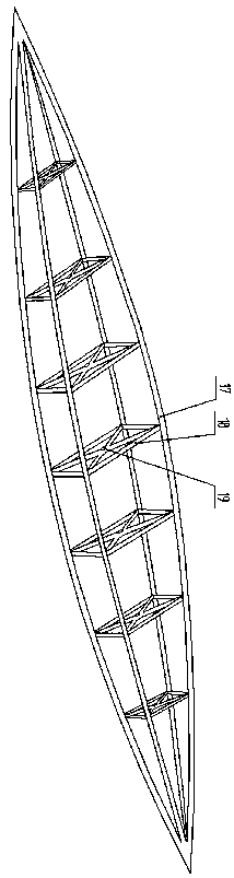
[0036] Such as Figure 3 to Figure 6 As shown, a shuttle-shaped arch used in Embodiment 1 includes a support beam 17 and a fastening beam frame 18, and the horizontal cable-shaped arch will increase the cable hole 19; its structure is to divide the traditional arch body into a The above beams are connected by several fastening beams 18 at a certain distance to form a shuttle-shaped structure with a wide middle and gradually narrowing towards the two ends. The plane where the fastening beams 18 are located is perpendicular to the axis, and the axis is the line connecting the two ends of the rod. , the fastening beam frame 18 is composed of an outer fastening beam and an inner fastening beam, but when the number of support beams 17 is two, the fastening beam frame 18 is only the only fastening beam and does not distinguish between the outer and the inner, but it can be composed of several This planar bar body is connected in parallel to form a shoulder-carrying three-dimensional...

Embodiment 3

[0038] Such as Figure 7 As shown, a ballistic structure sling 10 for the suspension arch bridge of Embodiment 1 includes a rope 20, a casing 21 and a pipe buckle block 22; the outside of the rope 20 is covered with a casing 21, and the rope 20 passes through the two ends of the casing 21 and connects with the pipe buckle block 22, and the outer periphery of the rope 20 is close to the inner periphery of the casing 21 and can be moved, and there is a force pushing the pipe buckle block 22 at both ends of the casing 21 The structural design principle of bullet-resistant structure sling 10 is based on: the extruding deformation of material is less than tensile deformation, thereby when sling bearing tension is less than sling inner rope 20 prestressed tensions, deformation is minimal, can strengthen bridge body rigidity.


PUM


Abstract

The invention discloses a suspension and arch combined bridge, and belongs to the field of bridge architecture design. The suspension arch combined bridge comprises arch supporting suspension cables,bridge supporting suspension cables, a spindle-shaped rod arch, a cable bent tower, a bridge span and anti-elasticity structural suspension ropes, and is characterized in that one ends of the arch supporting suspension cables are fixed at the two ends of a horizontal spindle-shaped arch rod separately and coincide with each other in the horizontal spindle-shaped arch rod body, and non-overlappingsections are erected on the cable bent tower; the spindle-shaped rod arch is supported and stabilized through the anti-elasticity structural suspension ropes; each of two groups of inclined arch rodsis connected to be in a V shape; the two ends of each of the two arch supporting suspension cables are fixed at the foot parts of different inclined arch rods in different groups; and the bridge supporting suspension cables support the bridge span with the end connecting points of the spindle-shaped arch rods as the bearing points by utilizing the anti-elasticity structural suspension ropes. According to the suspension and arch combined bridge, the problems that in the prior art, the span length of the rope bridge is limited by the rope quality, the lengths of the arch rods are restricted by the bending force under gravity and conventional arch rods have poor anti-vibrating and anti-bending capacities under the force effect are solved; besides, the wind resistance problem caused by the tensile elasticity of the ropes, namely the rigidity problem of the bridge and the stabilization problem of the rod arch are also solved.

Description

technical field [0001] The invention belongs to the field of bridge architectural design, in particular to a suspension arch composite system bridge. Background technique [0002] At present, there are only three types of bridges with spans of 600 meters: cable-stayed bridges, suspension bridges, or bridges with a combination of the two. The requirements for load-bearing ropes are very strict. If the self-weight of the bridge is too reduced, there will be safety hazards on the bridge deck, and the wind resistance performance will also deteriorate, so the span is limited, that is, the span of the bridge is limited by the quality of the ropes. Secondly, the ropes have too much elasticity. The rope bridge It is difficult to improve its own rigidity, and it is difficult to meet the relevant requirements of high-speed train operation. This will also cause potential safety hazards in wind resistance and anti-resonance of the bridge body. In addition, the load of the rope bridge is...

Claims


Application Information

Patent Timeline
Patent Type & Authority Patents(China)
IPC IPC(8): E01D12/00
Inventor 张圳霖
Owner 张圳霖
Why Eureka
Try Eureka