Device for the lateral stabilization of the spine

a lateral stabilization and spine technology, applied in the field of lateral stabilization devices of the spine, can solve the problems of crushing or deformation, degeneration of adjacent disks, and inability to provide actual dynamic stabilization of the vertebrae, and achieve the effect of stabilizing the vertebrae and being more reliable over tim

Active Publication Date: 2012-08-21
CLARIANCE SAS
View PDF10 Cites 0 Cited by
  • Summary
  • Abstract
  • Description
  • Claims
  • Application Information

AI Technical Summary

Benefits of technology

[0008]The object of the present invention is to propose a device for the lateral stabilization of the spine that reproduces the anatomical movements of the vertebrae more faithfully, is more effective for stabilizing the vertebrae to be treated and is more reliable over time.
[0010]The fact that the two vertebral elements of the device according to the invention are guided one relative to the other by the guide surfaces, which are delimited by those elements and cooperate one with the other by sliding bearing, makes it possible to confer on the device precise kinematic behavior that is stable over time. The imposed kinematics, namely a rotary movement between the two vertebral elements about the centre of rotation positioned, in a predetermined manner, in the disk space, ensures that the intervertebral articulating movements induced when the spine is stressed are guided effectively in order to be quasi-identical with, or at least as similar as possible to, normal anatomical behavior of the spine. In that manner, the cooperation of the lateral guide surfaces can allow a satisfactory intervertebral spacing to be retained, while maintaining a predetermined vertical spacing of the vertebrae. The device according to the invention accordingly bears the majority, or even the totality, of the stresses applied to the intervertebral disk, which remains mobile. Furthermore, implantation of the device according to the invention is found to be particularly simple: the mobilities particular to the device reside substantially, or even exclusively, in the region of the guide surfaces carried by the two vertebral elements, the anchoring positions, preferably lateral, of which in the two vertebrae to be treated are chosen and fixed by the surgeon. Since those guide surfaces extend laterally relative to the spine, surgical actions are concentrated in lateral zones relative to the spine.

Problems solved by technology

However, this type of operation of arthrodesis of the vertebrae leads to degeneration of the adjacent disks, on which it is subsequently necessary to operate.
This movable assembly adapts to a certain development of the kinematic behavior of the spine, for example as it grows, but does not provide actual dynamic stabilization of the vertebrae and accordingly does not prevent, for example, crushing or deformation of the intervertebral disks.
The kinematics imposed on the vertebrae is accordingly very different from the normal anatomical behavior of the spine, with considerable risks that the intervertebral disk will be pinched, or even crushed, at least in its anterior portion.
However, the use of that type of dynamic device is found to be difficult in practice.
Dimensioning of the flexibility of the joining elements is difficult because it must be adapted to each patient according to his pathology and morphology and, in the long term, the resilient behavior of those elements changes.
If those parameters are poorly controlled, it is not possible to ensure that a kinematics appropriate to the spine is respected, which can lead to poor stabilization of the intervertebral space and to aggravation of the damage that it is desired to treat.

Method used


Image

  • Device for the lateral stabilization of the spine
  • Device for the lateral stabilization of the spine
  • Device for the lateral stabilization of the spine

Examples


Embodiment Construction

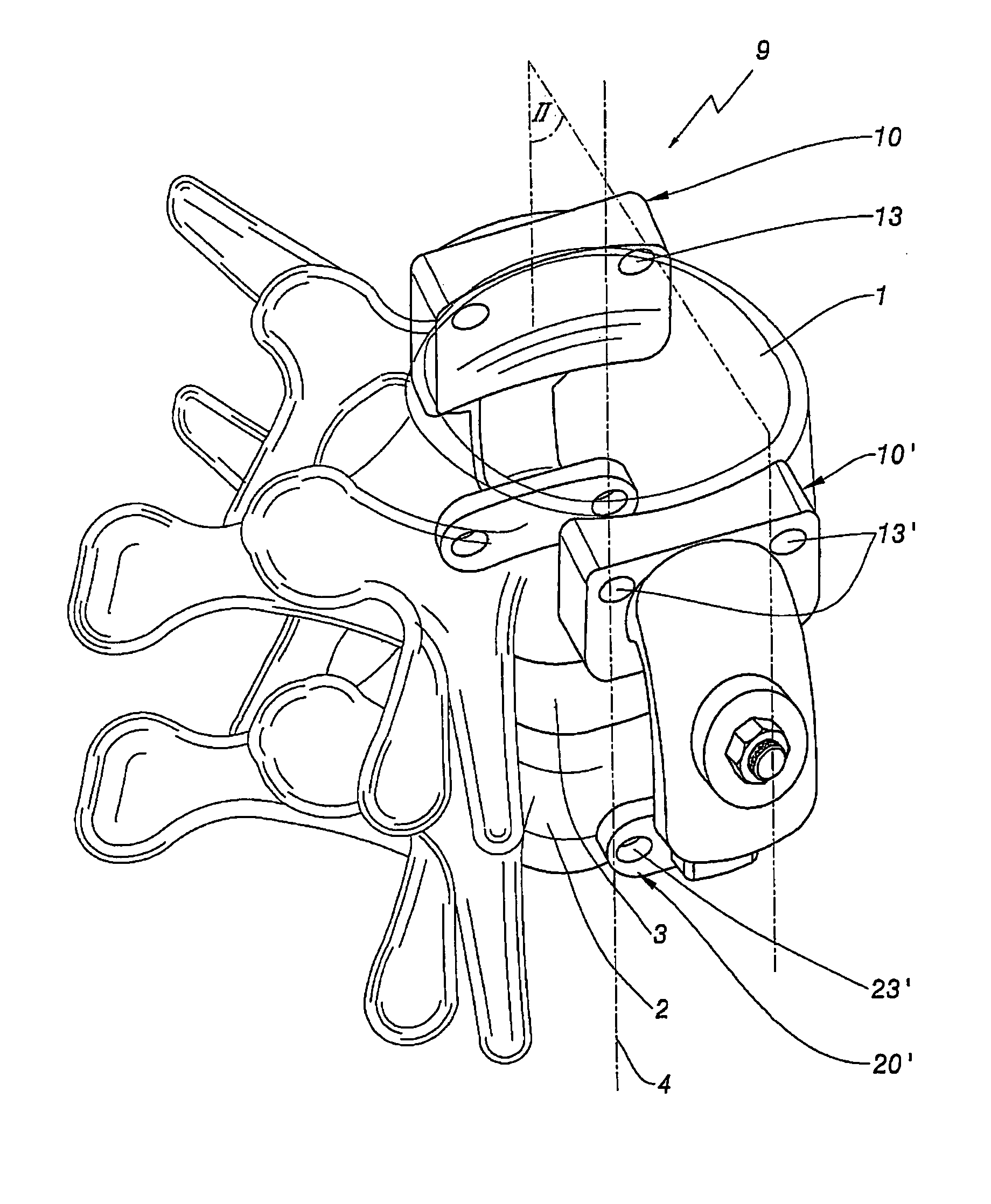
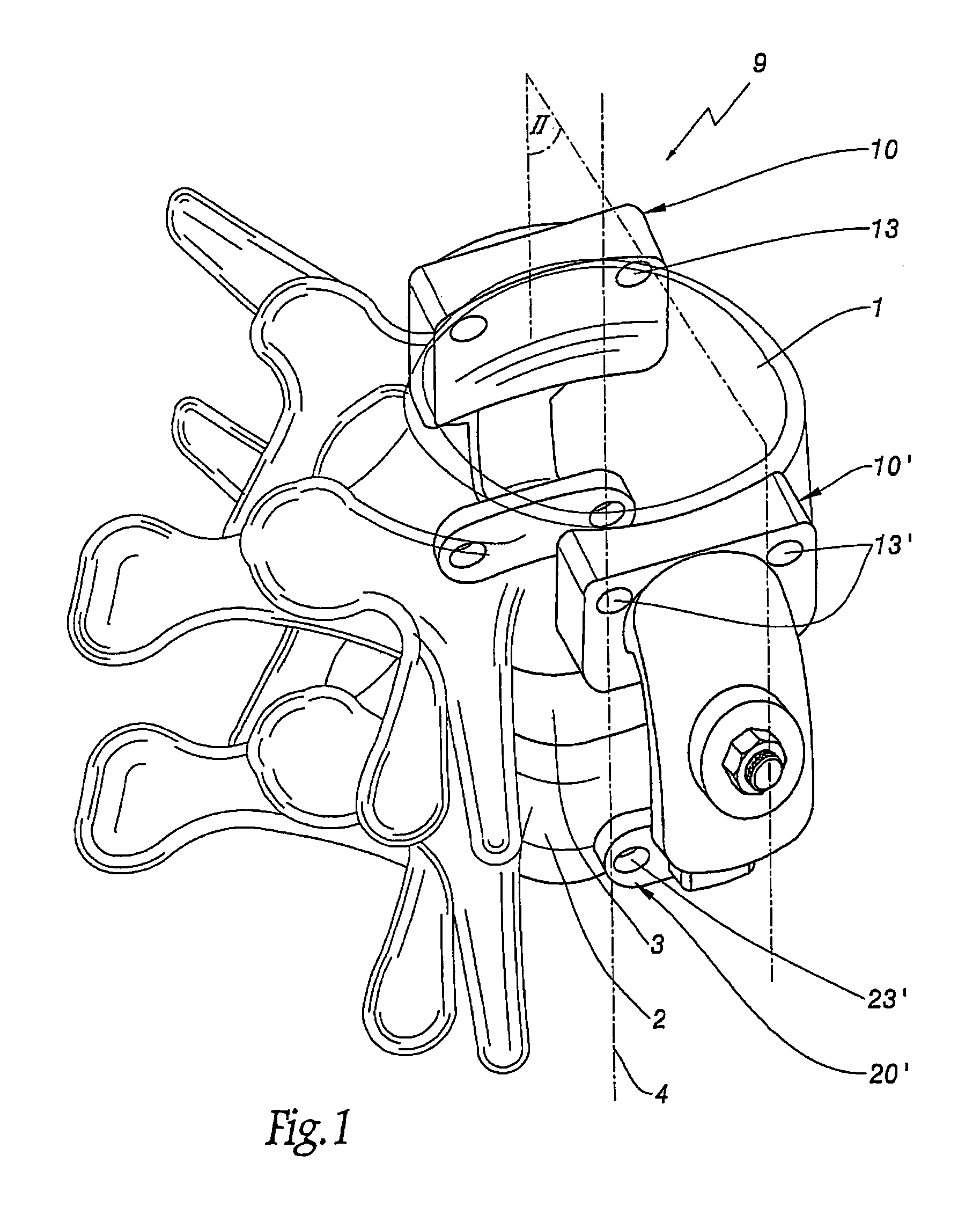
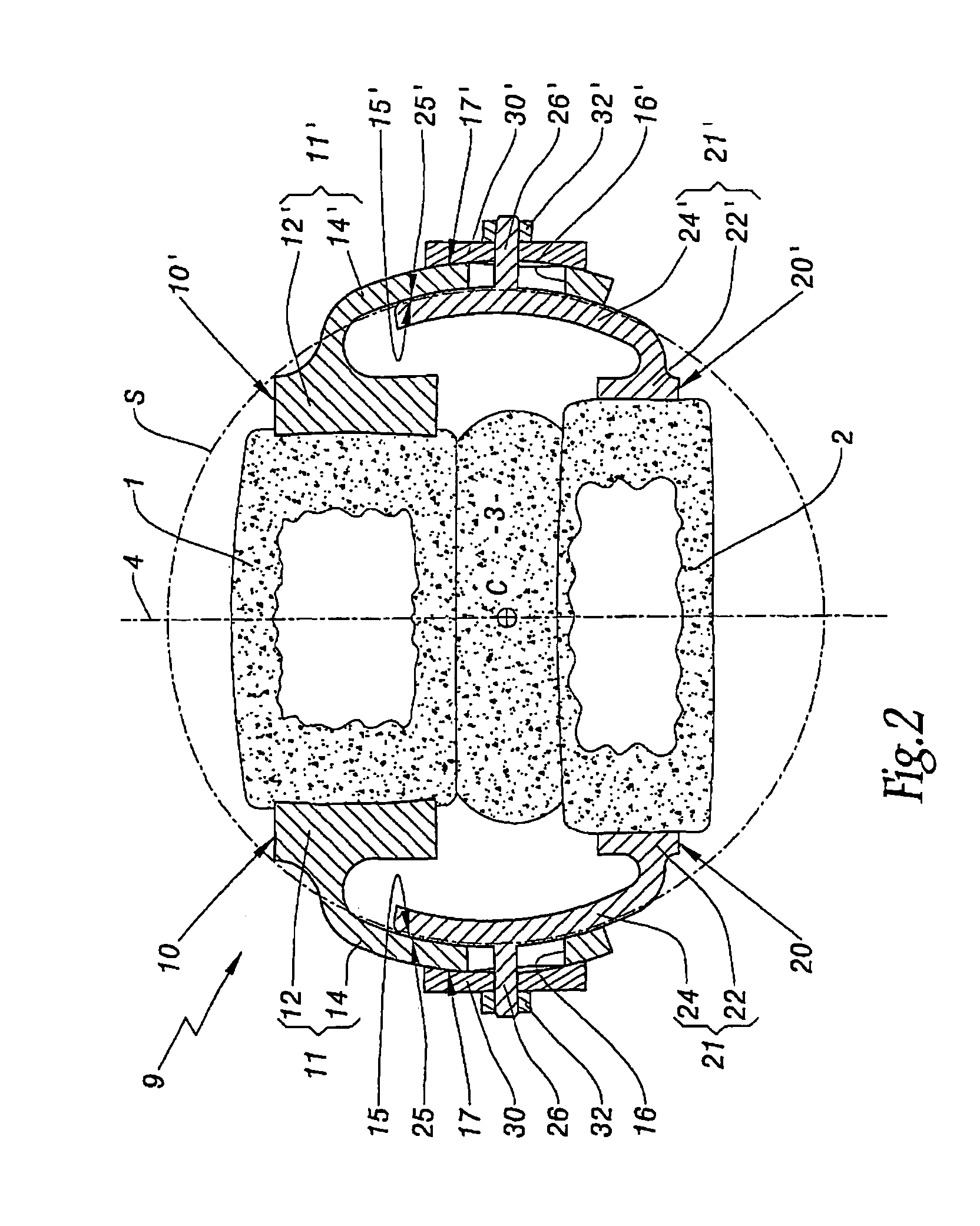
[0027]FIGS. 1 and 2 show, in diagrammatic form, two adjacent vertebrae 1 and 2 of a lumbar spine of a human being, which vertebrae are separated by an intervertebral disk 3 according to the longitudinal direction 4 of the spine. For convenience, the remainder of the description is oriented relative to the vertebrae in their anatomical position, that is to say the terms “posterior” or “rear”, “anterior” or “front”, “right”, “left”, “upper”, “lower”, etc. are to be understood relative to the spine of the patient standing upright. Likewise, the term “sagittal” corresponds to a direction in the anteroposterior direction, vertically on the median line of the spine, while the term “medial” corresponds to a direction substantially perpendicular to the sagittal plane of the spine, directed towards the spine, the term “lateral” corresponding to the opposite direction.

[0028]FIGS. 1 and 3 show a device 9 for the dynamic stabilization of the vertebrae 1 and 2, which device is implanted on the l...


PUM


Abstract

The device (9) comprises vertebral elements (10, 20, 10′, 20′) adapted to be fixed to the same lateral side of the bodies of at least two adjacent vertebrae (1, 2), the elements being associated in pairs that are provided to be associated with the left and right sides of the vertebrae. In order to guide the vertebrae effectively and stably, in order, in use, to reproduce an articulating intervertebral joint, the two elements of each pair delimit respective surfaces (15, 25, 15′, 25′) for the relative guiding of those elements, which surfaces are adapted, when the elements are implanted on their corresponding vertebra, to extend generally along the same lateral side of the body of the vertebrae and to rest and slide one against the other in such a manner that the surfaces define a center of rotation (C) about which the two elements are able to turn one relative to the other.

Description

BACKGROUND OF THE INVENTION[0001]1. Field of the Invention[0002]The present invention relates to a device for the lateral stabilization of the spine, which device is to be implanted along the vertebral column in the region of one or both of its left and right lateral sides, in order to stabilize at least two vertebrae one relative to the other. Such stabilization is desirable especially within the context of the treatment of degenerative or traumatized spine. The invention relates more particularly to the treatment of the dorsolumbar spine, but is likewise applicable to the treatment of the cervical spine.[0003]2. Brief Description of the Related Art[0004]For the treatment of an intervertebral instability, a first known possibility comprises fusing two adjacent vertebrae, which amounts to depriving those two vertebrae of their relative freedom of movement. Totally rigid assemblies are implanted for that purpose in a fixed manner along the spine in order permanently to block the arti...

Claims


Application Information

Patent Timeline
Patent Type & Authority Patents(United States)
IPC IPC(8): A61B17/70
CPCA61B17/7019
Inventor TORNIER, ALAINFERRARI-GOSSET, IRENE
Owner CLARIANCE SAS
Why Eureka
Try Eureka