
LED signal with side emitting status indicators

a technology of status indicators and led signals, applied in the field of signals, can solve the problems of insufficient light reaching the side emitting status indicators, failure to provide a failsafe indication to a train operator, and the leds providing a light signal in a primary direction to an oncoming motorist are not working properly, so as to achieve accurate side emitting status indications.

Active Publication Date: 2005-03-31
DIALIGHT CORP
View PDF6 Cites 19 Cited by
  • Summary
  • Abstract
  • Description
  • Claims
  • Application Information

AI Technical Summary

Benefits of technology

[0005] One object of the present invention is to provide a novel signal, such as a railway indicating signal that utilizes an LED light source and that provides an accurate side emitting status indication.
[0008] Accordingly, a more specific object of the present invention is to provide a novel LED signal with side emitting status indicators that provides a true indication of the light provided in a primary light output direction.

Problems solved by technology

In such a case, since the LEDs provide substantially directional light, in a device such as a railway light with side emitting status indicators, there is typically insufficient light reaching the side emitting status indicators for a train operator to view because of the directional nature of the LEDs.
However, that approach does not provide a failsafe indication to a train operator since those additional LEDs may not always operate the same as the primary LEDs providing the light signal in a primary direction to an oncoming motorist.
That is, the situation may arise that the LEDs providing a light signal in a primary direction to an oncoming motorist are not properly working, but different side facing LEDs providing light in a secondary direction to side emitting status indicators are properly working.

Method used


Image

  • LED signal with side emitting status indicators
  • LED signal with side emitting status indicators
  • LED signal with side emitting status indicators

Examples


Embodiment Construction

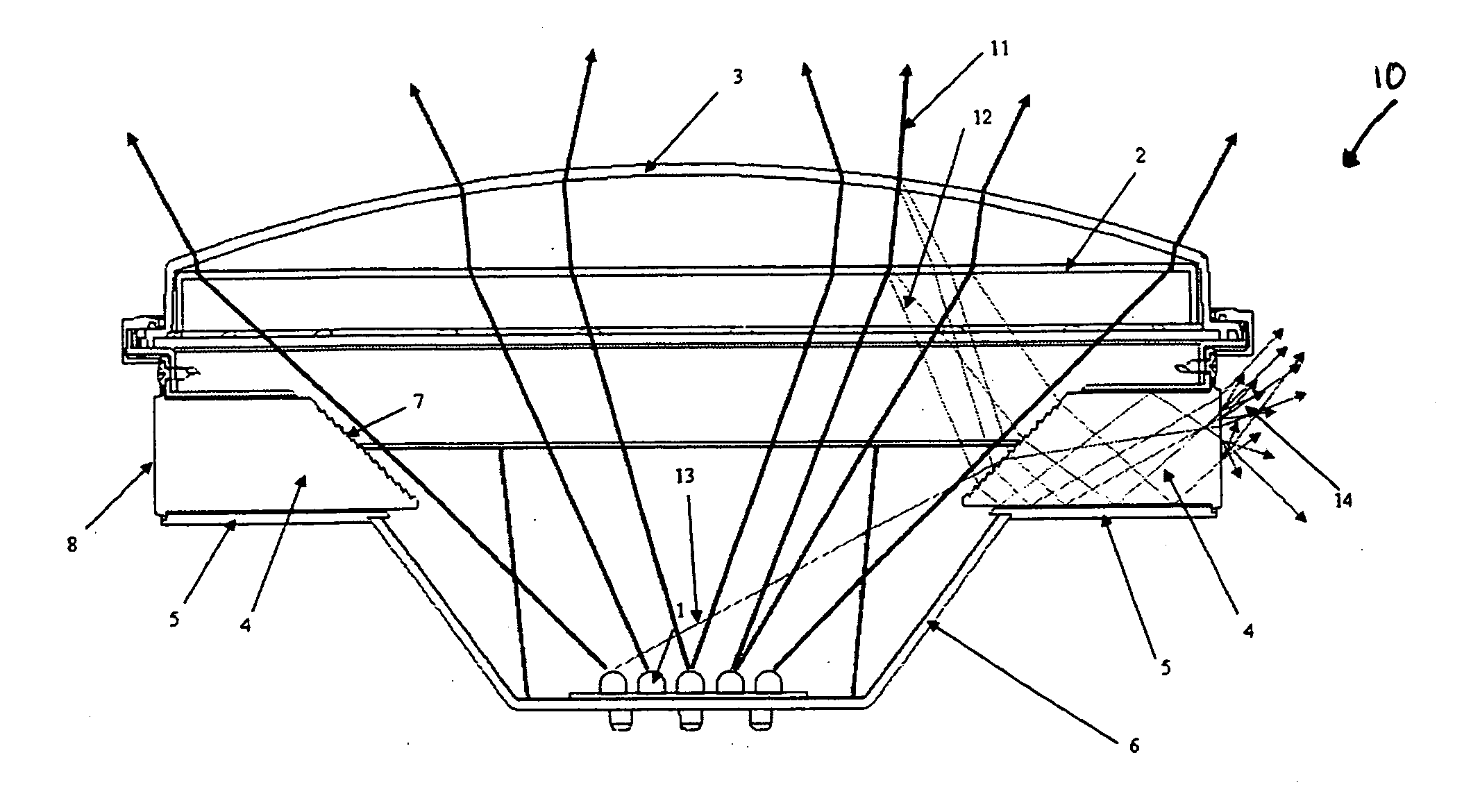
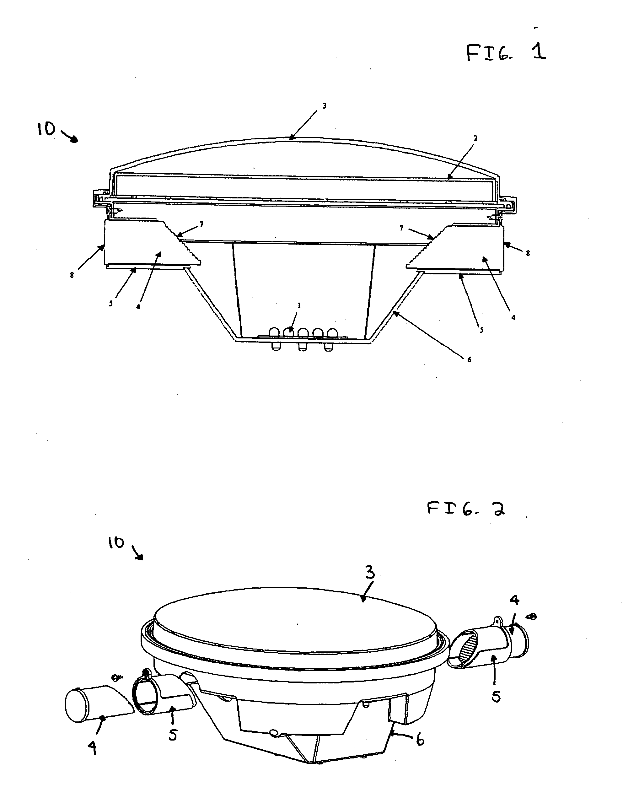
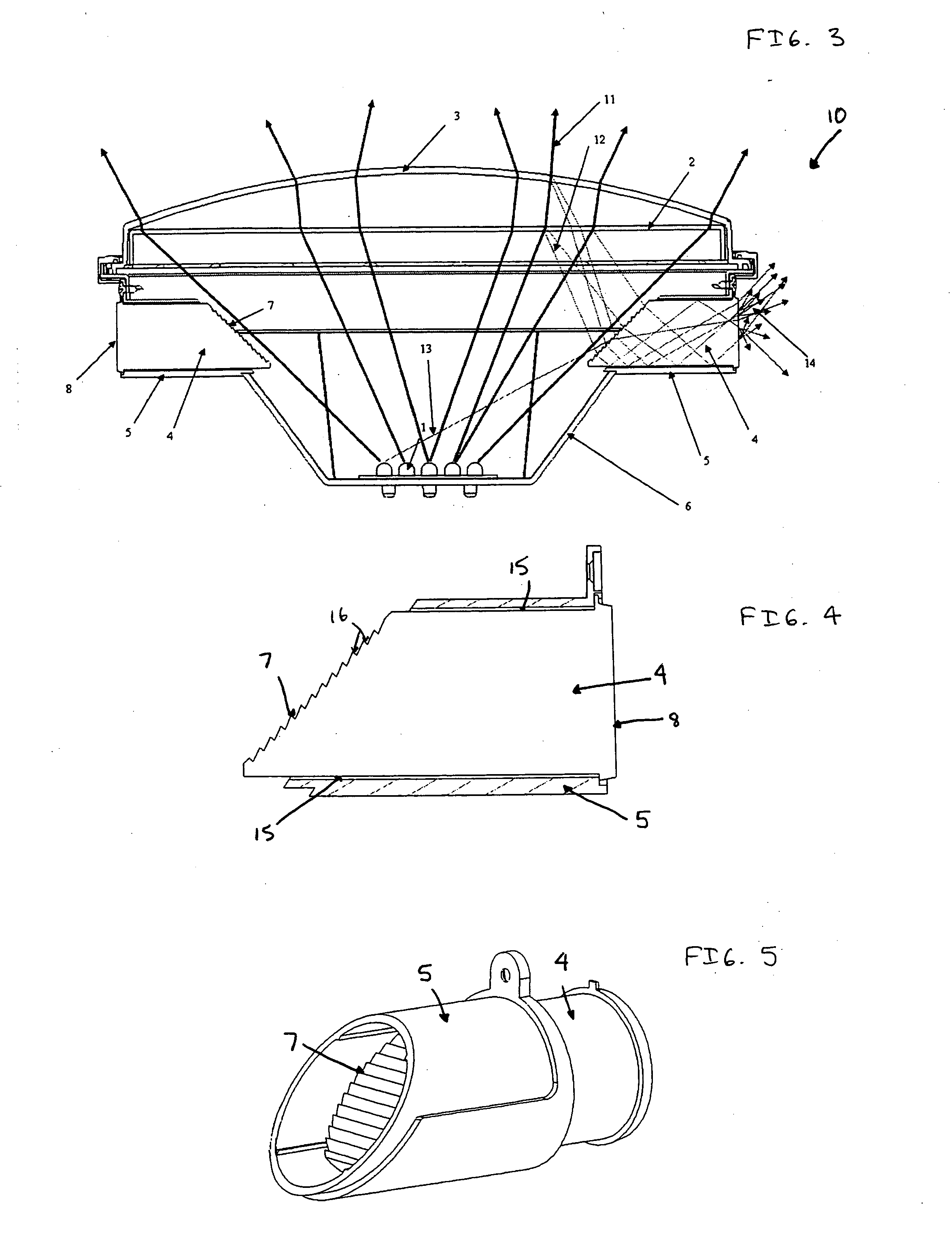
[0016] Referring now to the drawings, wherein like reference numerals identify identical or corresponding parts throughout the several views, and more particularly to FIGS. 1 and 2 thereof, views of a light device 10 of the present invention are shown. FIG. 1 shows an internal view of the dialight device 10, and FIG. 2 shows the light device 10 from a perspective view with certain elements exploded out.

[0017] As shown in FIGS. 1 and 2, the light device 10 includes an overall housing 6 that serves to house each of elements of the light device 10. The housing 6 can be formed of any suitable metal or plastic material. The light device 10 also includes a plurality of light emitting diode (LED) light sources 1. The number of LEDs 1 can vary based on the specific type of LEDs utilized.

[0018] The light device 10 also includes two lenses of an inner lens 2 and an outer lens 3. Light output from the LEDs 1 predominantly passes through the inner lens 2 and the outer lens 3 in a primary dire...


PUM


Abstract

A light device including side emitting status indicators that provide a true indication of whether light is being output in a primary output direction. The light device includes a light source of at least one LED configured to generate light in the primary output direction. The light generated by the at least one LEDs passes through a lens device, that may also reflect a portion of the light generated from the at least one LED. Collection optics are provided to capture a portion of the generated light and / or the reflected portion of the light generated from the light source, and are configured to output the captured generated and / or reflected light in a direction other than the primary direction, i.e., in a direction for the side emitting status indicators.

Description

BACKGROUND OF THE INVENTION [0001] 1. Field of the Invention [0002] The present invention relates to a signal that includes side emitting status indicators, and in particular in which the signal includes an LED light source. Such a signal can find application, for example, as a railway indicating signal. [0003] 2. Discussion of the Background [0004] A typical railway indicating signal utilizes an incandescent light bulb as a light source. Such a railway signal may be employed at a railway crossing. In that type of signal the light emitted from the incandescent light bulb passes through at least one red lens to provide a primary red signal to an oncoming motorist crossing the rail tracks. Also, two additional light ports, one on each side, may be provided to provide objective evidence to a train operator that the light bulb is properly outputting light to the oncoming motorist. That is, an operator on the train can view light output from the additional light ports to confirm that the...

Claims


Application Information

Patent Timeline
IPC IPC(8): B61L5/18B61L15/02F21S8/00F21V1/00F21V13/04
CPCB61L2207/02B61L5/1809
Inventor YOU, CHENHUAADINOLFI, JOHN T.KULBERG, KURT A.PICCIOTTI, MICHAEL F.
Owner DIALIGHT CORP
Learn More