Ostomy appliance

a technology for ostomy and ossomy, which is applied in the field of ostomy appliances, can solve the problems of high undesirable ballooning of bags, increased risk of leakage, and embarrassing ballooning for users

Inactive Publication Date: 2005-03-31
COLOPLAST AS
View PDF9 Cites 50 Cited by
  • Summary
  • Abstract
  • Description
  • Claims
  • Application Information

AI Technical Summary

Benefits of technology

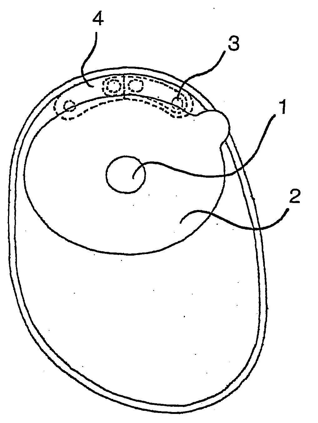
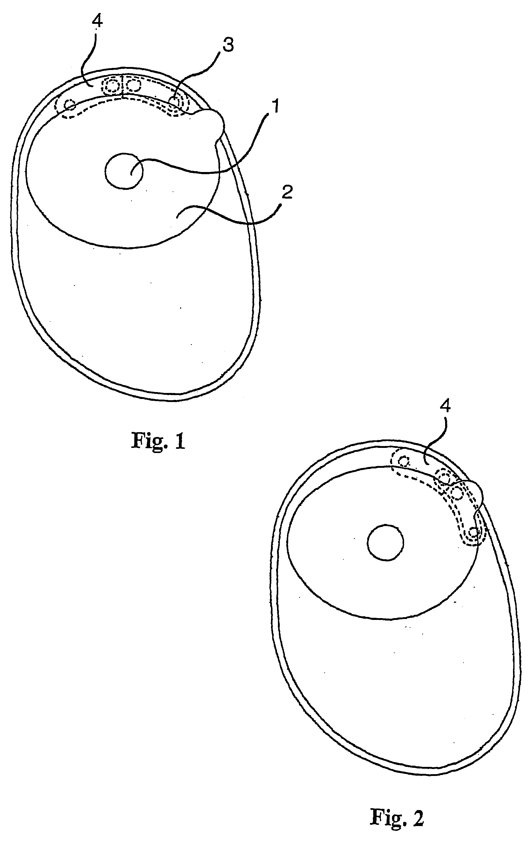
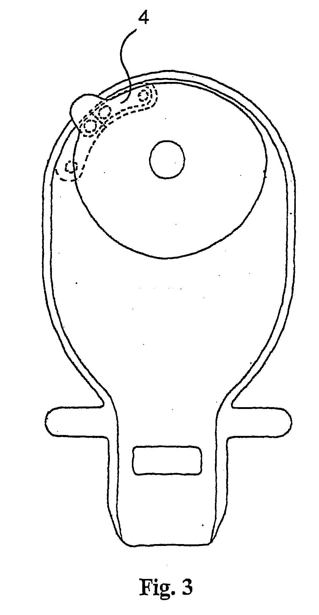
[0018] The invention relates in a first aspect to an ostomy appliance comprising a front wall and a rear wall of flexible material forming a bag, the rear wall having an opening into the bag by which waste material can enter the bag and one of the walls has one or more vents through which gas may escape from the bag and having a filter covering said vent wherein gas inlet and outlet openings are provided in communication with a filter body, the arrangement being so that in use gas flows through the filter from the inlet opening to the outlet opening, such gas flow being confined to said filter body.

Problems solved by technology

When the inlet opening of the filter is blocked, the gas discharged into the ostomy appliance cause ballooning of the bag which is highly undesirable for several reasons.
Ballooning will be embarrassing for the user as the bag will bulge and there is an increased risk of leakage which is unacceptable for the user.
However, such slits may open if the pressure is high giving free flow of gas and liquid through the layer of sheet material.
However, it has been found that, especially for ostomates having an ileostomy and especially at night when they turn in bed, there is a risk of directly pressing faeces in the receiving bag against the inlet opening(s) of the filter and that the pressure may be sufficiently high to force the front of visceral material through a foam material covering a single inlet opening of the vent and past the inlet opening of the filter to cause a blocking of a microporous oleophobic membrane covering the inlet opening of the vent as the one or all of the passage way(s) communicate with one and the same compartment.

Method used


Image

  • Ostomy appliance
  • Ostomy appliance
  • Ostomy appliance

Examples


example

[0079] Preparation of a filter part of a filter device according to the invention.

[0080] A coal package consisting of a filter body of foam impregnated with coal and having a width of 7 mm, a length of 40 mm and a thickness of 2 mm, sealed between two barrier foils comprising the layers EVA, PVDC, EVA and CPE (chlorinated ployethylene), was produced by heat welding the layers around the filter body.

[0081] Two hydrophobic and oleophobic membranes were welded over preformed holes placed close to each other in a laminated barrier sheet consisting of EVA, PVDC, EVA and CPE. To the other side of the sheet, the coal package was welded having an inlet hole aligned with one of the membranes only. This entity is defined as the coal / membrane package.

[0082] Two pieces of polyether foam with a width of 8 mm, a length of 33 mm and a thickness of 1 mm were placed on a piece of non-woven fabric leaving an area in between free. The non-woven layer was heat welded to the filter package enclosing ...


PUM


Abstract

An ostomy appliance comprising a front wall and a rear wall of flexible material forming a bag, the rear wall having an opening into the bag by which waste material can enter the bag and one of the walls has one or more vents through which gas may escape from the bag and having a filter covering said vent wherein gas inlet and outlet openings and provided in communication with a filter body, the arrangement being so that in use gas flows through the filter from the inlet opening to the outlet opening, such gas flow being confined to said filter body, wherein the gas inlet opening to the filter is provided with at least two separate and independent closed pathways having separated inlet openings communicating with the bag and separate and independent outlet openings communicating with the inlet opening of the filter, and wherein each of the outlet openings of the separate pathways are covered by a microporous membrane shows improved resistance against blocking of the inlet opening of filter.

Description

BACKGROUND OF THE INVENTION [0001] 1. Field of the Invention [0002] The present invention relates to an ostomy appliance comprising a deodorising filter, in particular ostomy bags, and to a filter device. [0003] In connection with surgery for a number of diseases in the gastrointestinal tract a consequence is, in many cases, that the patient is left with a stoma such as a colostomy, an ileostomy or an urostomy in the abdominal wall for the discharge of the effluents or waste products of the body, which are conveyed through the colon, the ileum or the ureter. The discharge of visceral contents including intestinal gases cannot be regulated at will, and for that purpose the opening may be closed with a closure means, e.g. a tampon or a magnetic closure, or the patient will have to rely on an appliance to collect the material emerging from such opening in the form of a receiving bag which is later emptied and / or discarded at suitable times. [0004] Ostomy appliances are well known. Such...

Claims


Application Information

Patent Timeline
Patent Type & Authority Applications(United States)
IPC IPC(8): A61F5/441A61F5/445
CPCA61F5/441
Inventor BULOW, MARTIN VONKRISTENSEN, MOGENS GULDAGER
Owner COLOPLAST AS
Why Eureka
Try Eureka