Window regulator

a window regulator and wire type technology, applied in the direction of wing operation mechanisms, door/window fittings, constructions, etc., can solve the problems of wire b>39/b> generating interference noise, and is ineffective use of door panel space,

Inactive Publication Date: 2005-04-07
SHIROKI KOGYO CO LTD
View PDF5 Cites 15 Cited by
  • Summary
  • Abstract
  • Description
  • Claims
  • Application Information

AI Technical Summary

Benefits of technology

[0019] In short, according to the invention, the wire is arranged along the first frame, the upper frame and the second frame. Moreover, what resides in the space ins...

Problems solved by technology

As a result, there arises a problem that it is impossible to make effective use of the space in the door panel.
This arrangement raises a problem that it is impossible to make ...

Method used


Image

  • Window regulator
  • Window regulator
  • Window regulator

Examples


first embodiment

[0043] the invention will be described with reference to FIG. 3 to FIG. 10. This embodiment is applied to a left-hand front door in a sedan type automobile.

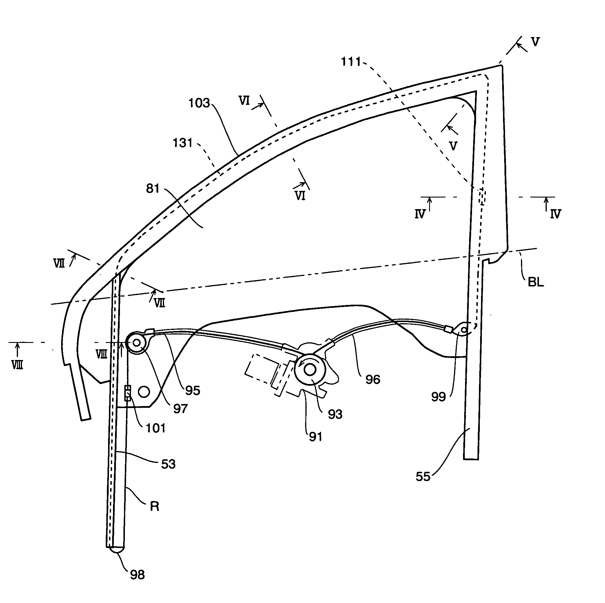
[0044] In FIG. 3, reference letters BL designate a door belt line, which extends on the upper end of a door panel. The door is provided on its front side with a front frame 53 or a first frame extending in the directions for a door glass 81 to go up and down. The door is provided on its rear side with a rear frame 55 or a second frame extending in the directions for the door glass 81 to go up and down. The upper portion of the front frame 53 and the upper portion of the rear frame 55 are spanned with an upper frame 103.

[0045] As shown in FIG. 4 to FIG. 8, the front frame 53, the rear frame 55 and the upper frame 103 have different sectional shapes, but each of them is provided with an ornamental portion 61 exposed to the outside, a hollow member 63 having a closed sectional shape, and a glass run mounting portion 65 for mounting...

second embodiment

[0071] the invention will be described with reference to FIG. 11 to FIG. 14.

[0072] What this embodiment is different from the first embodiment resides in that the drum 93 is disposed at a portion of the front frame 53 on the lower side of the belt line BL, and the remaining constructions are similar to those of the first embodiment. Therefore, the overlapping description will be omitted by designating the same portions in FIG. 11 to FIG. 14 as those in FIG. 3 to FIG. 10 by the common reference numerals.

[0073] At the lower portion of the front frame 53, as shown in FIG. 11, there are disposed the drum 93 and the motor 91 for driving it rotationally. As shown in FIG. 12, more specifically, a bracket 201 is attached to the lower portion of the front frame 53. In this bracket 201, there are formed motor mounting holes 203, into which screws 205 belonging to the motor 91 are inserted. The not-shown nuts are fastened on the leading ends of the screws 205. As a result, the motor 91 is fix...

third embodiment

[0087] the invention will be described with reference to FIG. 15 and FIG. 16.

[0088] As shown in FIG. 15, the door is provided on its front side with a front frame 253 or a first frame extending in the directions for a door glass 251 to go up and down. The door is provided on its rear side with a rear frame 255 or a second frame extending in the directions for the door glass 251 to go up and down.

[0089] Since the front frame 253 and the rear frame 255 have identical sectional shapes, the sectional shape of the front frame 253 will be described with reference to FIG. 16 while the description of the sectional shape of the rear frame 255 being omitted. As shown in FIG. 16, the front frame 253 is provided with: a base portion 257; a first side face portion 261 and a second side face portion 263 bent from the two sides of the base portion 257 and extending toward the outer side of a car body 259; and a first ceiling portion 267 and a second ceiling portion 269 bent toward each other from...


PUM


Abstract

A window regulator to be disposed in a vehicle comprises: a first frame disposed on one side of the longitudinal direction of a door and extending in the directions for a door glass to go up and down; a second frame disposed on the other side of the longitudinal direction of the door and extending in the upward and downward directions of the door glass; an upper frame disposed to span the upper portion of the first frame and the upper portion of the second frame; a wire tensed in an annular shape along the first frame, the upper frame and the second frame and having a return portion for a backward run in the first frame; a first wire fixing member disposed on one side of the longitudinal direction of the door glass and retained by the return portion of the wire to move along the first frame; a second wire fixing member disposed on the other side of the longitudinal direction of the door glass and retained by the wire portion to move along the second frame; and a drum disposed on the inner side of the door panel of the door and wound with a portion of the wire for moving the annularly tensed wire back and forth when it is turned.

Description

BACKGROUND OF THE INVENTION [0001] 1. Field of the Invention [0002] The present invention relates to a wire type window regulator to be disposed in a vehicle or the like for opening / closing a door glass. [0003] 2. Description of the Related Art [0004] As the related art of this kind, there can be exemplified the disclosure of JP-A-4-27093. This related art will be described with reference to FIG. 1. [0005] As shown in FIG. 1, a door is provided at its front portion with a guide rail 3, which extends in the directions for a door glass 1 to go up and down. The door is further provided at its rear portion with a guide rail 5, which extends in the directions for the door glass 1 to go up and down. [0006] Moreover, a roller 7 movably engages with the guide rail 3, and a roller 9 and a roller 11 movably engage with the guide rail 5. [0007] The door panel is provided in its central space with a guide rail 13 extending in the directions for the door glass 1 to go up and down. With this guid...

Claims


Application Information

Patent Timeline
IPC IPC(8): E05F11/38E05F11/48
CPCE05F11/385E05Y2900/55E05F2011/387E05F11/488
Inventor YAMAMOTO, KENJI
Owner SHIROKI KOGYO CO LTD
Why Eureka
Try Eureka