Coupling device

US20050072103A1Inactive Publication Date: 2005-04-07ULTIMATE DESIGN SOLUTIONS

Image

  • Coupling device
  • Coupling device
  • Coupling device

Examples


Embodiment Construction

[0104] There will now be described by way of example the best mode contemplated by the inventors for carrying out the invention. In the following description numerous specific details are set forth in order to provide a thorough understanding of the present invention. It will be apparent however, to one skilled in the art, that the present invention may be practiced without limitation to these specific details. In other instances, well known methods and structures have not been described in detail so as not to unnecessarily obscure the present invention.

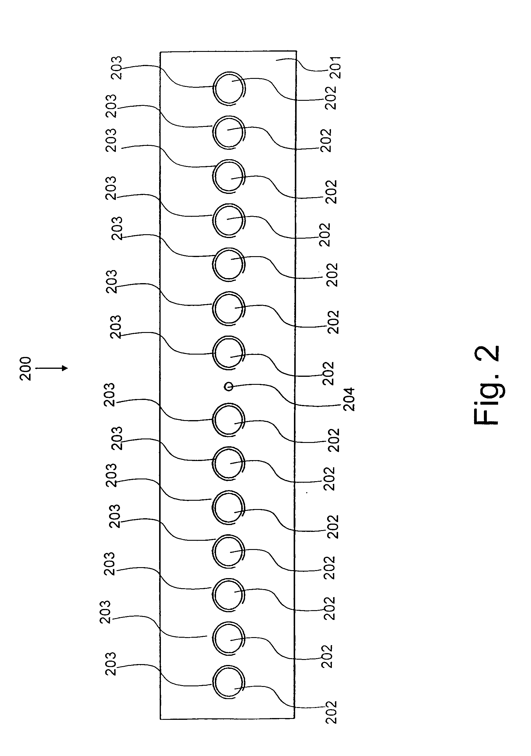
[0105] Referring to FIG. 2 herein there is illustrated a plan view of the bar coupling device according to the specific implementation of the present invention. The coupling device 200 comprises an elongate tubular body 201, a plurality of longitudinally spaced holes 202 and a centrally located hole 204, according to the specific implementation of the present invention. The elongate tubular body 201 is manufactured from a steel or s...


PUM


Abstract

A coupling device for the coupling of reinforcing bars, the coupling device comprising an elongate tubular body configured for receiving reinforcing bars, in particular their end portions, at least one recessed gripping surface being formed on an inner surface of the elongate tubular body, the recessed gripping surface comprising a plurality of teeth being configured to engage the reinforcing bars in response to the engagement of the reinforcing bars by a plurality of engaging bolts being adjustably positioned through the elongate tubular body.

Description

FIELD OF THE INVENTION [0001] The present invention relates to the coupling of bars, wires and cables, in particular but not exclusively, to the coupling of reinforcing bars used in structural concrete. BACKGROUND TO THE INVENTION [0002] There exists within the art apparatus and method for coupling reinforcing bars used in structural concrete, such coupling commonly involves the use of a tubular steel coupling body or sleeve configured to receive end portions of the reinforcing bars. Typically, the bars are held in place using a number of engaging bolts which engage into the surfaces of the bars wedging them against an inner surface of the tubular body thereby providing a couple. [0003] In particular, U.S. Pat. No. 5,046,878, GB 2220241 and EP 0554972 all disclose a reinforcing bar coupling system as detailed with reference to FIG. 1 herein. FIG. 1 herein illustrates a cross-sectional side elevation view of a bar coupling system found in the art comprising an elongate tubular body 1...

Claims


Application Information

Patent Timeline
07 Apr 2005
Publication
US20050072103A1
IPC
E04C5/16; F16B7/04
CPC
E04C5/165; Y10T403/551; Y10T403/5733; F16B7/0426
Inventors
HOPWOOD, IAN