Fluid jet for providing fluid under pressure to a desired location

a technology of fluid jets and pressure, which is applied in the direction of functional valve types, machines/engines, transportation and packaging, etc., can solve the problems of reducing the cooling and lubricating effect of oil, /b> beginning to vacillate, and the pistons of gasoline engines, etc., to prevent the vacillation of the closure component, reduce fluid flow turbulence and aeration, and prevent the effect of vacillation

Active Publication Date: 2005-04-07
MD INVESTORS CORP
View PDF13 Cites 18 Cited by
  • Summary
  • Abstract
  • Description
  • Claims
  • Application Information

AI Technical Summary

Benefits of technology

[0017] Therefore, it is an object of the present invention to provide a fluid jet that prevents vacillation of the closure component so as to reduce fluid flow turbulence and aeration.

Problems solved by technology

The pistons of gasoline engines, diesel engines, and high performance engines become easily overheated during operation.
A particular disadvantage with the ball valve construction is that the ball 48 is unstable and is capable of lateral movement within the bore 38 as shown by arrows A and B. The unstable ball 48 begins to vacillate in response to the high-pressure oil flowing therearound.
Such vacillation agitates the oil causing aeration which decreases the cooling and lubricating effect of the oil.
While the piston valve design has advantages over the ball valve design, both designs are generally made from an excessive number of parts which are expensive to manufacture and difficult to assemble.

Method used


Image

  • Fluid jet for providing fluid under pressure to a desired location
  • Fluid jet for providing fluid under pressure to a desired location
  • Fluid jet for providing fluid under pressure to a desired location

Examples


Embodiment Construction

[0029] The present invention is directed to a fluid jet for providing fluid under pressure to a desired location. However, the following detailed description is directed to the preferred embodiment of the invention, an oil jet for use with an internal combustion engine for providing oil under pressure to a desired location. It should be understood that nothing in the following description of the preferred embodiment should limit the scope of the invention to the preferred embodiment.

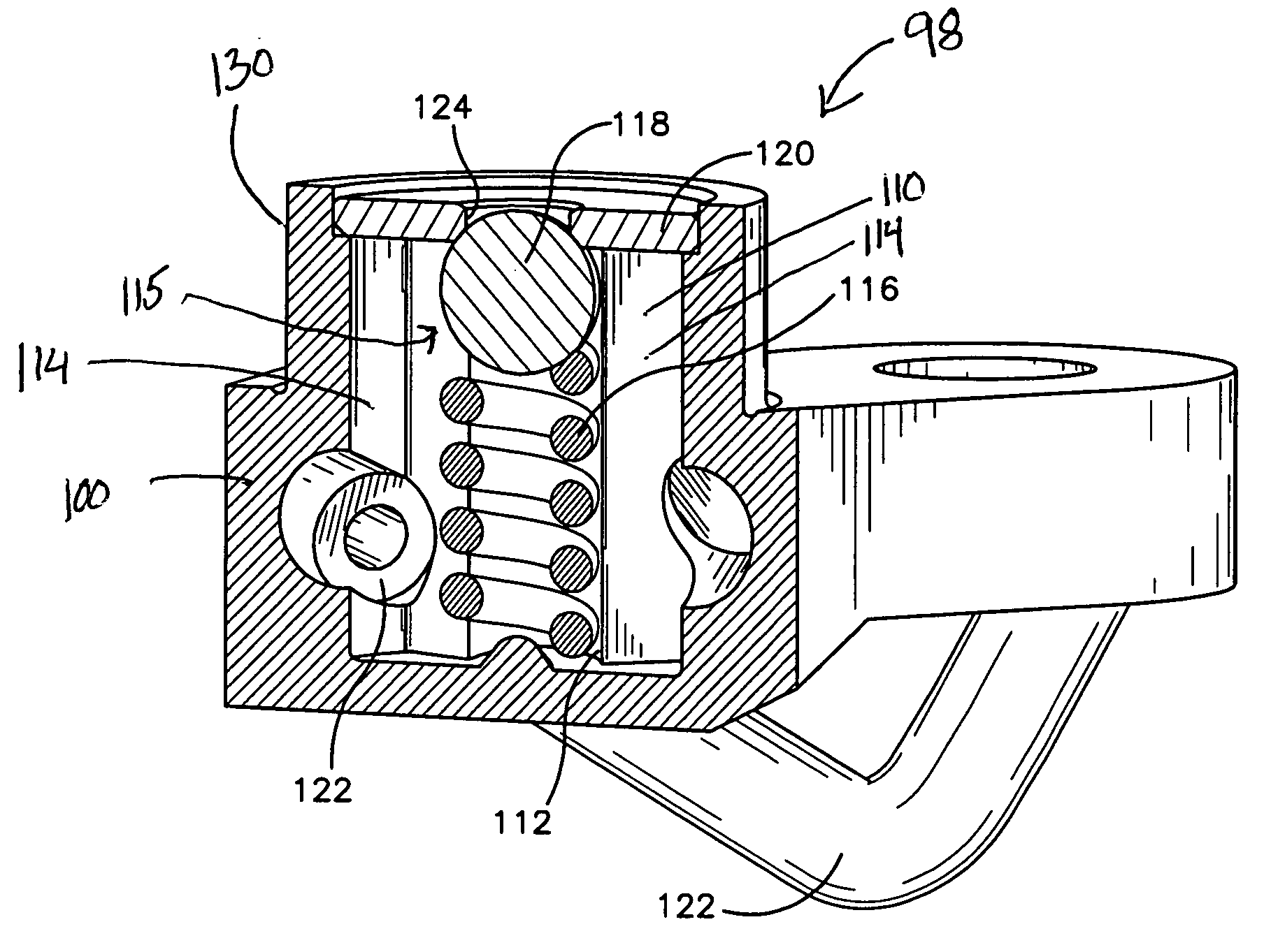
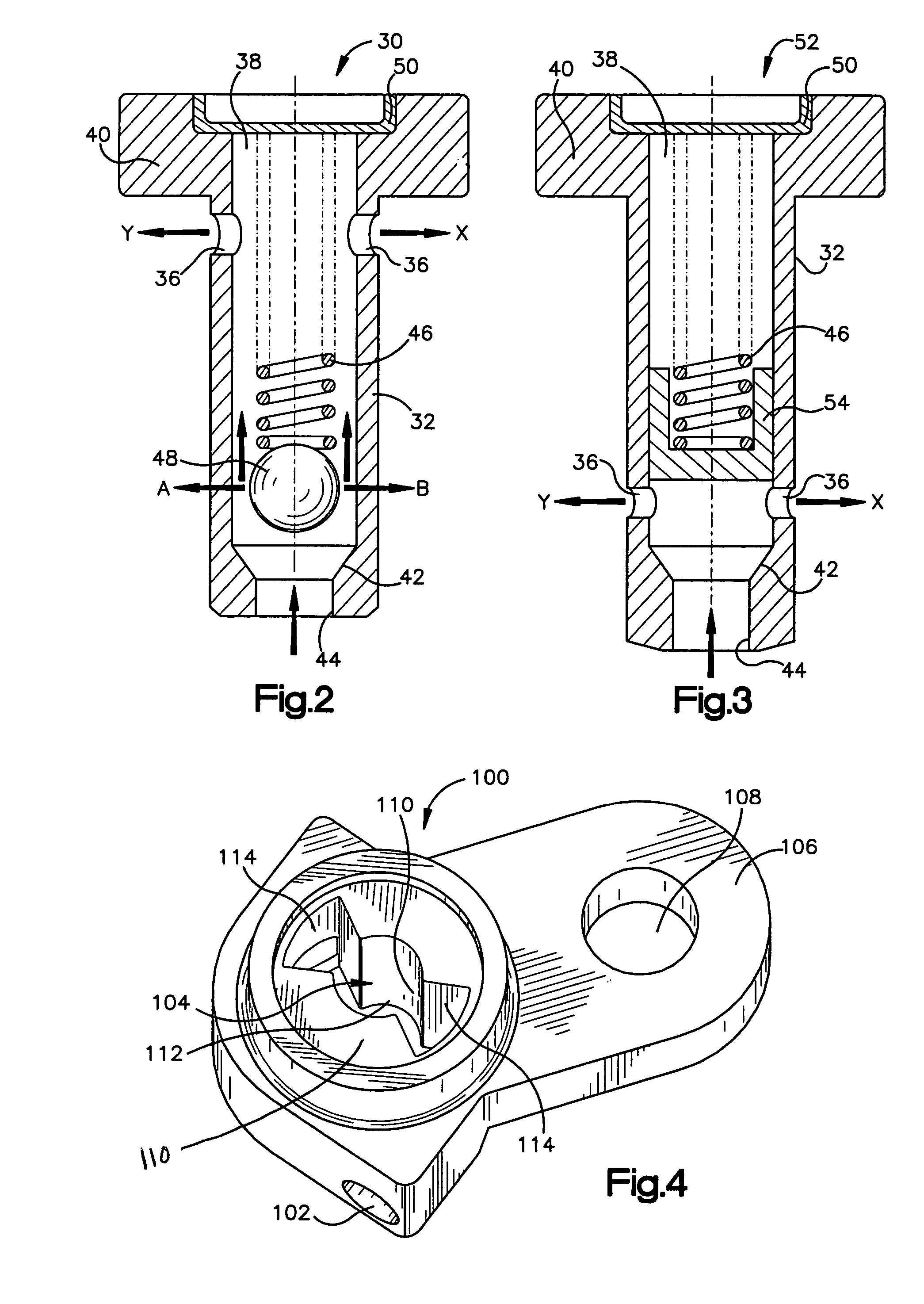
[0030] The preferred embodiment of the present invention will now be described with reference to FIGS. 4-6. As best shown in FIG. 5, an oil jet, generally designated as 98, according to the preferred embodiment of the present invention utilizes a valve body 100 having an integral valve element retaining region 112. Enclosed within the valve element retaining region 112 is a spring biased valve element 15 retained therein by a cap 120 connected to the valve body 100. A nozzle 122 is connected to the valv...


PUM


Abstract

A fluid jet for providing fluid under pressure to a desired location is disclosed wherein the valve body includes and integral valve element retaining region. Preferably, the valve body and integral valve element retaining region are die cast as a one-piece component. More specifically, the fluid jet includes a die cast one-piece valve body having a valve element retaining region extending longitudinally within at least a portion of the valve body, at least one fluid passage extending longitudinally within at least a portion of the valve body and in fluid communication with at least a portion of the valve element retaining region, and at least one fluid-exiting aperture through the valve body in fluid communication with the at least one fluid passage.

Description

CROSS REFERENCE TO RELATED APPLICATIONS [0001] This application claims the benefit of priority from U.S. Provisional Patent Application Ser. No. 60 / 501,472 filed on Sep. 9, 2003.FIELD OF THE INVENTION [0002] The present invention relates generally to fluid jets for providing fluid under pressure to a desired location, and more particularly, to a fluid jet having a valve element retaining region integrally formed with the valve body. BACKGROUND [0003] The pistons of gasoline engines, diesel engines, and high performance engines become easily overheated during operation. Pressure actuated oil jets have long been used to cool the under side of the pistons in such reciprocating engines. Such oil jets are often mounted in a bore on the underside of the engine block and receive oil under pressure from an oil gallery. These oil jets also incorporate a check valve to supply oil to the oil jet when a predetermined oil pressure is achieved and also prevent siphoning off of needed oil pressure...

Claims


Application Information

Patent Timeline
Patent Type & Authority Applications(United States)
IPC IPC(8): F01P3/08F16KF16K15/00F16K15/02F16K15/04
CPCF01P3/08F16K15/044F16K15/025Y10T137/7914Y10T137/7937Y10T137/7927
Inventor NETO, JOSE CORREA
Owner MD INVESTORS CORP
Why Eureka
Try Eureka