Precision measuring collision avoidance system

a collision avoidance and precision technology, applied in the field of sensor-based systems, can solve the problems of increasing the number of accidents, driving only in one spot at any one time, and traffic congestion on the road becoming more and more congested

Inactive Publication Date: 2005-04-07
ALTRA TECH
View PDF3 Cites 186 Cited by
  • Summary
  • Abstract
  • Description
  • Claims
  • Application Information

AI Technical Summary

Benefits of technology

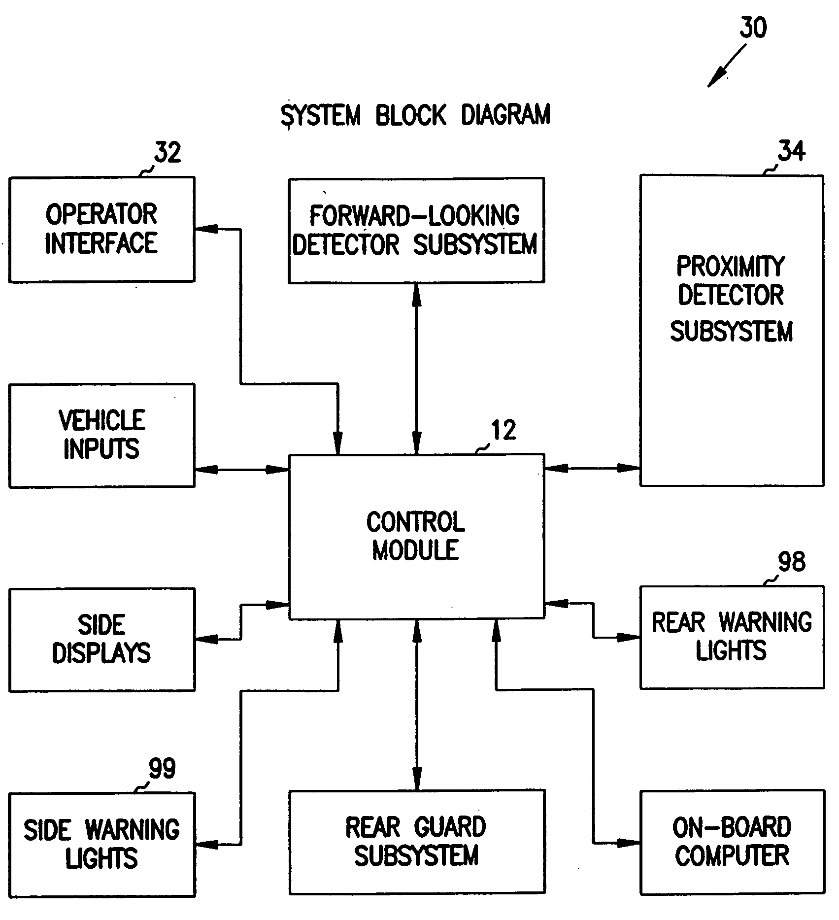
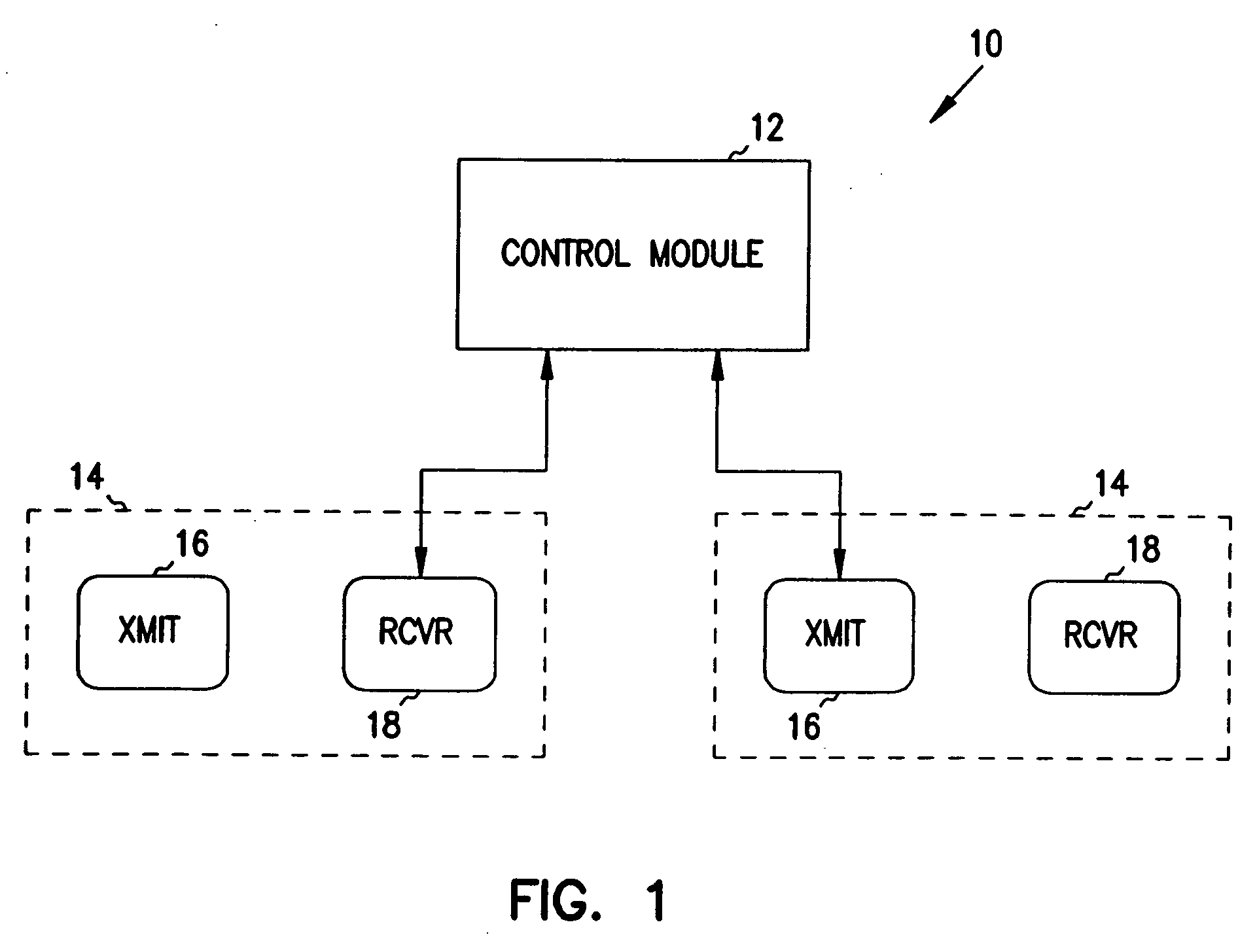
The present invention is a collision avoidance system. The collision avoidance system includes a control module, a first transmitting device connected to the control module, wherein the first transmitting device transmits a signal, a first receiving device connected to the control module, wherein the first receiving device receives a return of the signal transmitted from the first transmitting device and transmits a first return signal representative of the return to the control device, a second transmitting device connected to the control module, wherei

Problems solved by technology

The roads are becoming more and more congested with vehicular traffic.
As traffic congestion has increased, the number of accidents has also increased.
Some of these accidents can be traced to driver inattentiveness or to the failure of the driver to see another vehicle.
Mirrors, however, have a deficiency in that the driver can only look in one spot at any one time.
There is a similar problem with changing lanes.
Mirrors don't work well in changing lanes, particularly in tractor-trailer rigs, since, as soon as the rig begins to turn, the mirror that looked down along the side of the vehicle is directed into the side of the trailer and the driver is blinded to activity on that side of his truck.
The problem with backup alarms is that if you have somebody with a hearing problem, or if you had an immovable object such as a car or a trash container, the alarm isn't going to move that object out of the way.
The problem with the video system approach is that such systems are expensive (even if you use an inexpensive approach, it would likely cost into the $1,000-$1,500 price range) and video monitors mounted in the cab can distract the driver from what is happening outside his vehicle.
Finally, video lenses do not give depth perception.
So, when drivers are backing a vehicle, they don't know how close they are to an object they are trying to avoid.
A common problem with rear-mounted sensors to date is that sensors mount

Method used


Image

  • Precision measuring collision avoidance system
  • Precision measuring collision avoidance system
  • Precision measuring collision avoidance system

Examples


example

Deepest Hole

Suppose the following agreement matrix was generated with MST (rows) and sensor (columns) tracks. All possible standard differences between the MST and sensor data are calculated and placed into the matrix. For this example it will be assumed that all standard differences fall below the limiting value (step 1). Since this matdx contains more rows than columns, the matrix is transposed (step 2). Sensor⁢ ⁢DetectionsMSTTracks⁢ 12311.72.02.721.82.55.433.12.71.542.36.21.9⇒transpose⇒⁢MST⁢ ⁢Tracks  ⁢  ⁢  ⁢SensorDetections⁢ 123411.71.83.12.322.02.52.76.232.75.41.51.9

The difference between the minimum and next minimum values for each row is then calculated (step 5).

Row 1Row 2Row 3(next min) − (min) A:0.10.50.4

The largest value found (i.e. deepest hole) is 0.5 corresponding to Row 2 or Sensor Detection 2. This row is then examined to find the corresponding column (MST track) which has the minimum standard difference. The minimum is 2.0 corresponding to column 1. The smalles...


PUM


Abstract

A collision avoidance system including a control module, a first transmitting device connected to the control module, wherein the first transmitting device transmits a signal, a first receiving device connected to the control module, wherein the first receiving device receives a return of the signal transmitted from the first transmitting device and transmits a first return signal representative of the return to the control device, a second transmitting device connected to the control module, wherein the second transmitting device transmits a signal, and a second receiving device connected to the control module device, wherein the second receiving device receives a return of the signal transmitted from the second transmitting device and transmits a second return signal representative of the return to the control device, wherein the control module includes measurement circuitry used to measure the first and second return signals and display means for displaying a transverse location of an object as a function of said first and second return signals.

Description

BACKGROUND OF THE INVENTION 1. Field of the Invention The present invention relates generally to sensor-based systems, and more particularly to a multi-sensor collision avoidance system which combines data from two or more sensors to provide range, range rate, or location information. 2. Background Information The roads are becoming more and more congested with vehicular traffic. As traffic congestion has increased, the number of accidents has also increased. Some of these accidents can be traced to driver inattentiveness or to the failure of the driver to see another vehicle. What is needed is a system and method for warning drivers of possible problems before the problems result in an accident. Systems for making drivers aware of objects external to their vehicle have been around for a long time. Mirrors, and sometimes combinations of mirrors, are being used to reveal locations hidden to the driver's view (i.e.“blind spots”). Mirrors, however, have a deficiency in that the dr...

Claims


Application Information

Patent Timeline
IPC IPC(8): B60Q1/52G08G1/16
CPCB60Q9/006B60Q9/007B60Q9/008G01S7/003G01S13/726G01S13/878G01S2013/9389G01S2013/9364G08G1/16G08G1/161G01S2013/9378G01S2013/9382G01S13/931G08G1/165G08G1/166G01S2013/9324G01S2013/93272G01S2013/93273G01S2013/93275
Inventor GUNDERSON, RICHARD A.PARISI, MICHAEL AGORMAN, RICHARD P.MELIN, KURTIS W.
Owner ALTRA TECH
Why Eureka
Try Eureka