Panel, in particular floor panel

a technology for floor panels and panels, applied in the field of floor panels, can solve problems such as destroying relief, and achieve the effect of improving the appearance of the panel

Active Publication Date: 2005-04-14
KRONOTEC
View PDF99 Cites 64 Cited by
  • Summary
  • Abstract
  • Description
  • Claims
  • Application Information

AI Technical Summary

Benefits of technology

[0004] The invention improves the appearance

Problems solved by technology

The relief is destroyed dur

Method used


Image

  • Panel, in particular floor panel
  • Panel, in particular floor panel

Examples


Embodiment Construction

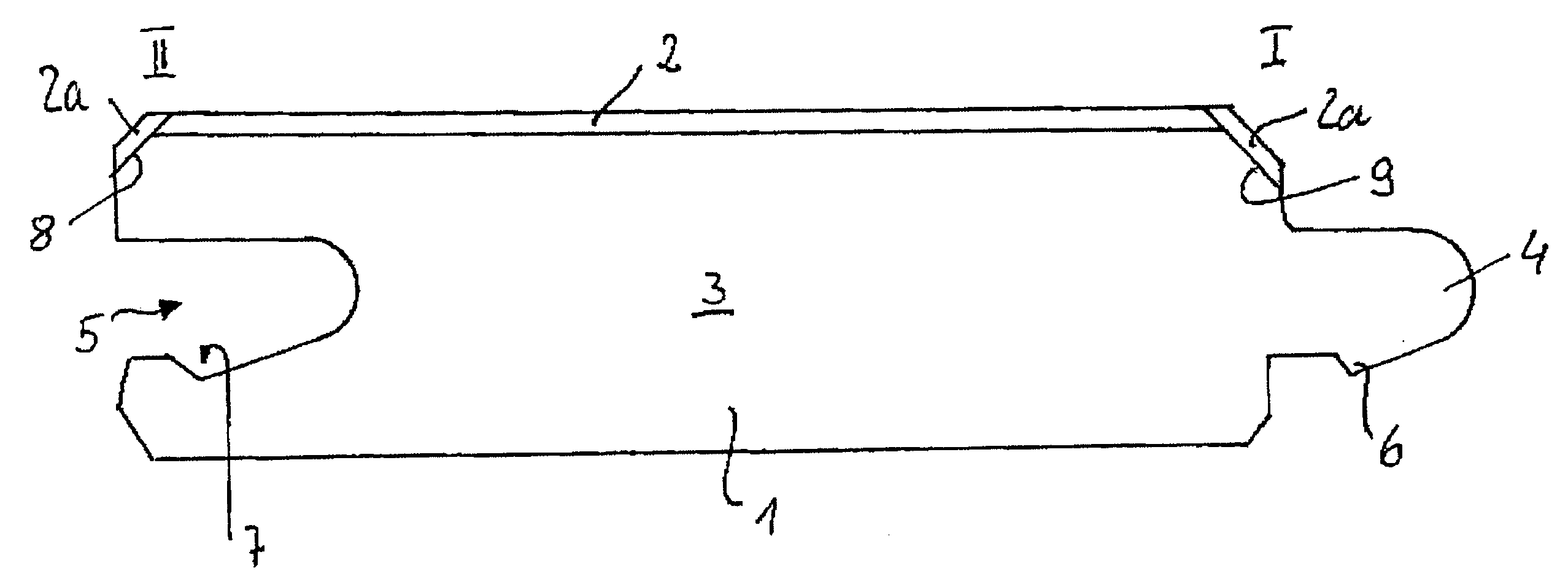
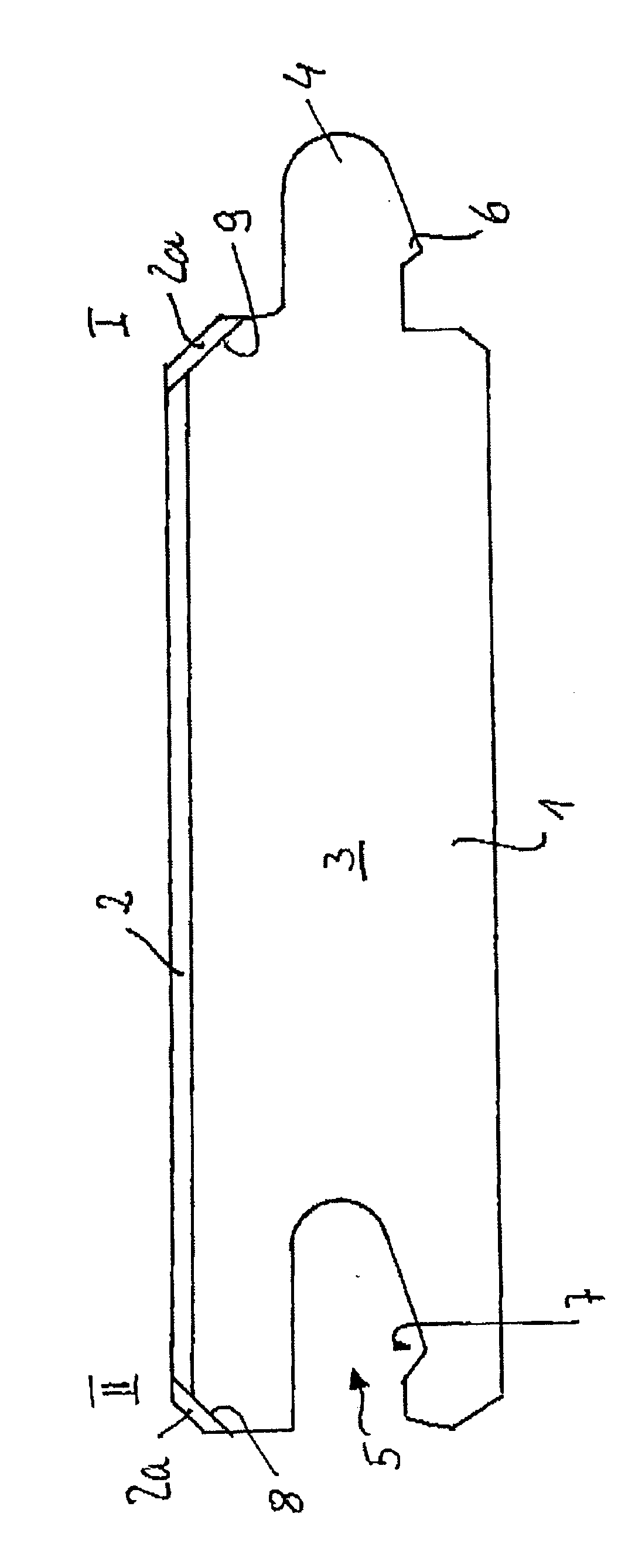
[0007] The decoration on the chamfer is preferably covered with a synthetic-resin layer, and the relief is stamped into the synthetic-resin layer. By virtue of this configuration, the appearance and feel are matched to the top side of the panel, with the result that it is possible to use conventional panels which have a stamped-in relief on their visible side.

[0008] The decoration is preferably printed directly onto the visible side of the panel and / or of the chamfer. This does away with the decorative paper or the carrier layer which is necessary for the transfer printing, as a result of which the production costs are reduced. Moreover, such a configuration makes it possible to dispense with the practice of applying a synthetic-resin layer first of all. In the case of conventional panels, corundum particles are introduced into the synthetic-resin layer, which is usually a melamine-resin-impregnated paper, in order to increase the abrasion resistance. These corundum particles resul...


PUM

PropertyMeasurementUnit
Structureaaaaaaaaaa

Abstract

The invention is directed to a panel, in particular floor panel, having a core made of a woodbased material and having a decoration applied to a visible side, the visible side being provided, on at least one side edge (I, II), with a chamfer running at an angle thereto, and the chamfer likewise being provided with a decoration, characterized in that a relief is stamped into the surface of the chamfer.

Description

FIELD OF INVENTION [0001] The invention relates to a panel, in particular a floor panel, having a core made of a woodbased material, in particular MDF or HDF, and having a decoration applied to a visible side, the visible side being provided, on at least one side edge, with a chamfer running at an angle thereto, and the chamfer likewise being provided with a decoration. [0002] Such a panel is known, for example, from WO 01 / 96688. BACKGROUND DESCRIPTION [0003] In the case of such panels, the decoration is applied to a paper web which, together with a synthetic-resin layer, is pressed with the visible side of the panel. The chamfer is produced by virtue of the side edge being milled. A corresponding decoration strip is then adhesively bonded to the chamfer or the decoration is printed onto the visible side of the chamfer by transfer printing. In particular if the floor panel is made to look like wood, that is to say the printed-on decoration is provided with a structure (differences i...

Claims


Application Information

Patent Timeline
IPC IPC(8): E04F15/02E04F15/04E04F15/10
CPCE04F15/02E04F15/02033Y10T428/24438E04F2201/0115E04F15/04
Inventor LEWARK, MATTHIAS
Owner KRONOTEC
Why Eureka
Try Eureka