Static mixer-heat exchanger

a technology of heat exchanger and mixer, which is applied in the direction of indirect heat exchanger, stationary tubular conduit assembly, light and heating apparatus, etc., can solve the problems of increasing the cost of mixing operation, increasing the pressure drop experienced by users of such devices, and having to pay a price for using such expedients

Inactive Publication Date: 2005-04-14
KOMAX SYST
View PDF9 Cites 93 Cited by
  • Summary
  • Abstract
  • Description
  • Claims
  • Application Information

AI Technical Summary

Problems solved by technology

Mixers can contain active elements such as paddles and rotors although it is quite common to provide static elements whereby the turbulent flow of the fluids in and around these elements enhance fluid mixing without the need for moving parts which inherently add to the cost of the mixing operation both in terms of power requirements and labor intensive maintenance procedures.
It has been determined that the improvement in heat transfer obtained by tube inserts for laminar flow applications is usually in the range of two to five times. However, the use of such devices significantly increases the pressure drop experienced and thus one using such expedients must pay a price.
However, it has been determined that the device shown in FIG. 2 does not provide a good utilization of the exchanger shell available volume, less, in fact, than the conventional tube and shell heat exchanger.

Method used


Image

  • Static mixer-heat exchanger
  • Static mixer-heat exchanger
  • Static mixer-heat exchanger

Examples


Embodiment Construction

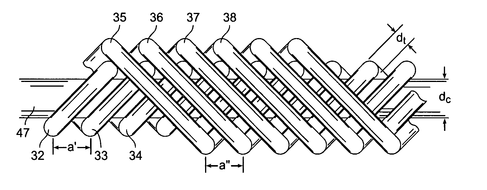
As noted previously, the present invention is directed to a device for effecting heat transfer from a first fluid medium to a second fluid medium and for enhancing mixing and uniform distribution of the second fluid medium within the confines of a conduit. This can perhaps best be visualized by referring to FIG. 4. Device 40 is shown as consisting of conduit 41 having a cross section and longitudinal axis 42. The conduit is provided with an inlet 43 for introduction of the first fluid within conduit 41 and an outlet 44 for passing the first fluid from the conduit. The conduit further is provided with inlet 45 for the introduction of the fluid product as well as downstream exit 46 for passing the product fluid from conduit 41.

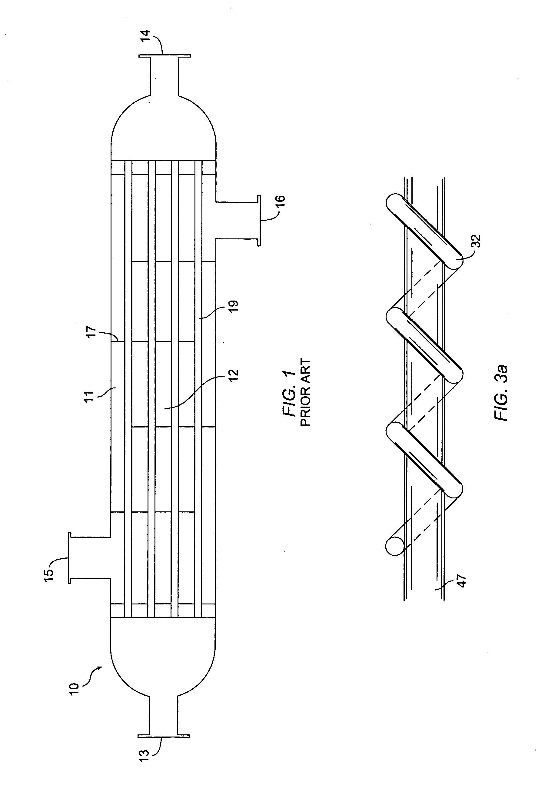
Referring further to FIG. 4, the device is provided with core pipe 47, which is also depicted as element 47 in FIG. 3. As shown, the core pipe is located approximately at longitudinal axis 42. The device is further provided with a series of tubes which, for t...


PUM


Abstract

A device for effecting heat transfer from a first fluid medium to a second fluid medium and for enhancing mixing and uniform distribution of the second fluid medium within the confines of a conduit. The device includes providing a core pipe for receiving the first fluid medium and a series of helically wound tubes in fluid communication with the core pipe along the longitudinal axis of the conduit. The second fluid passes within the conduit and is mixed by virtue of the static mixing effect of the helically wound tubes and engages in heat transfer as a result of the intimate contact between the second fluid, the core pipe and the helically wound tubes.

Description

TECHNICAL FIELD OF THE INVENTION The present invention is directed to a device for effecting heat transfer from a first fluid medium to a second fluid medium and for enhancing mixing and uniform distribution of the second fluid within the confines of a conduit. BACKGROUND OF THE INVENTION It is notoriously well known in the processing of fluid streams to employ static mixers and heat exchangers as enhancements in promoting product uniformity and adjusting product temperature. Mixers can contain active elements such as paddles and rotors although it is quite common to provide static elements whereby the turbulent flow of the fluids in and around these elements enhance fluid mixing without the need for moving parts which inherently add to the cost of the mixing operation both in terms of power requirements and labor intensive maintenance procedures. Many static mixers rely on a mixing element configuration that presents a set of interstices to the product flow. Elements of this type...

Claims


Application Information

Patent Timeline
Patent Type & Authority Applications(United States)
IPC IPC(8): F28D7/02F28D7/16
CPCF28D7/024
Inventor KING, LEONARD TONY
Owner KOMAX SYST
Why Eureka
Try Eureka