Dual conduction heat dissipating system for a spacecraft

Inactive Publication Date: 2005-04-14
ALCATEL LUCENT SAS
View PDF12 Cites 2 Cited by
  • Summary
  • Abstract
  • Description
  • Claims
  • Application Information

AI Technical Summary

Benefits of technology

[0014] This significantly improves and homogenizes the distribution of heat between the collectors and the wall.

Problems solved by technology

Traveling wave tubes produce a large amount of heat which must be dissipated into space.
The radiators being independent of each other, the tubes are virtually independent of each other from a radiating point of view, which is not beneficial in terms of dissipation, environment and mode of operation.
This is unsatisfactory given the ever increasing power that must be dissipated, which generally goes hand in hand with increasing complexity of the arrangements, especially on the east-west faces of the spacecraft (presence of large antenna reflectors and their support mechanism (hold on release mechanisms—HRMs), large send / receive sources and associated radiators, thruster supports, adjacent collectors, etc.), which significantly reduces the efficiency of radiation into space.
In other words, because of the insufficient dissipation of heat, and given the technological limitations of its traveling wave tubes, each spacecraft must be specifically configured and / or have the RF power of its payload limited.

Method used


Image

  • Dual conduction heat dissipating system for a spacecraft
  • Dual conduction heat dissipating system for a spacecraft
  • Dual conduction heat dissipating system for a spacecraft

Examples


Embodiment Construction

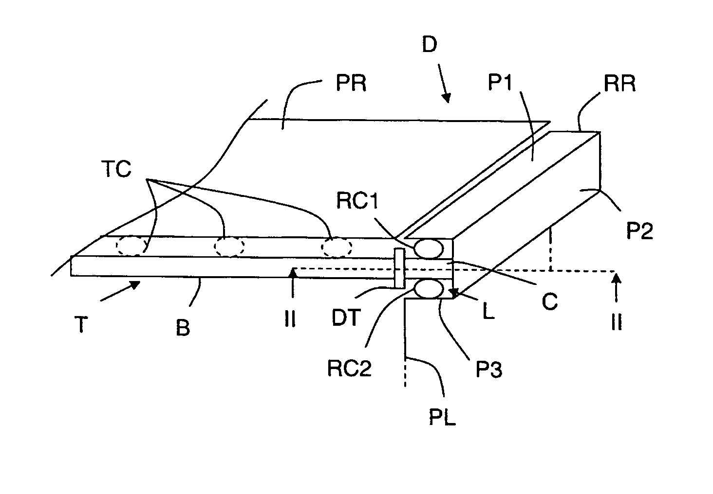
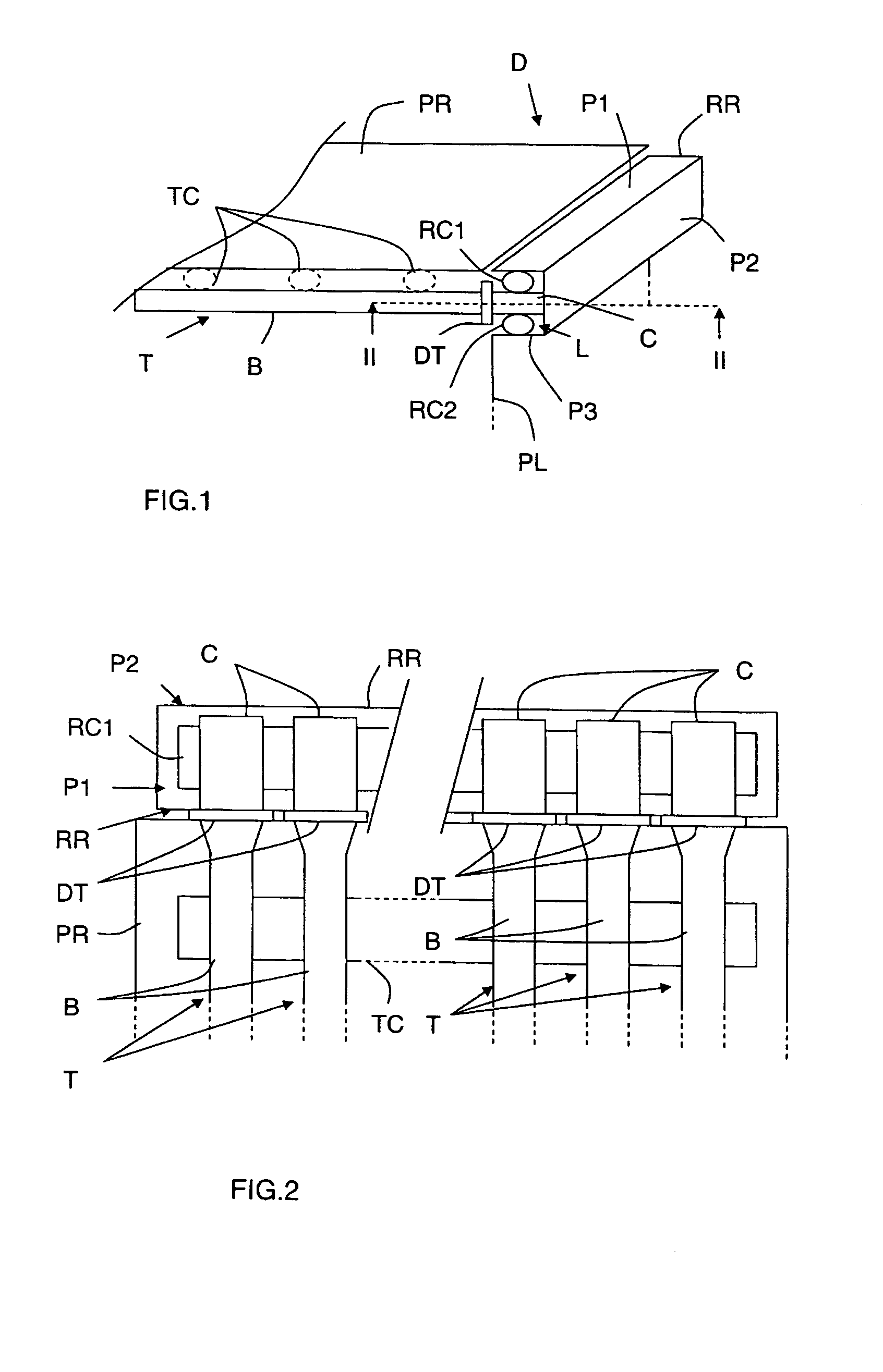
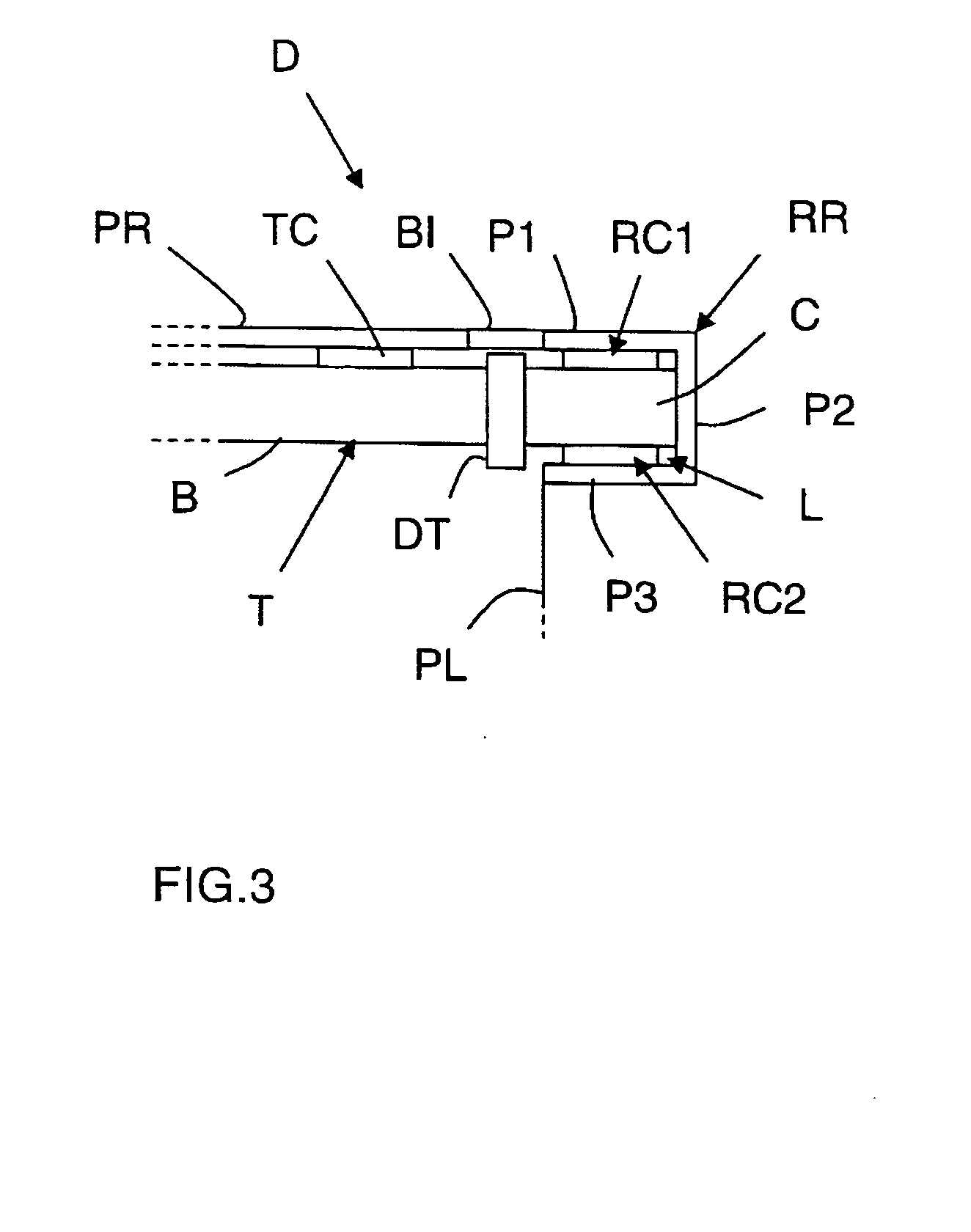
[0025] The appended drawings constitute part of the description of the invention and may, if necessary, contribute to the definition of the invention.

[0026] An object of the invention is to dissipate a large part of the heat produced by onboard amplifier tubes of a spacecraft.

[0027] In the present context the term “spacecraft” means any type of craft or vehicle traveling in space, either in orbit (low or high Earth orbit or geosynchronous orbit) or free of the gravitational field of the Earth, and adapted to transmit signals after amplifying them, and in particular satellites, especially telecommunication or remote sensing satellites, space probes, orbiting space stations and spaceships.

[0028] Hereinafter, by way of illustrative example, the spacecraft is a telecommunication satellite.

[0029] A telecommunication satellite comprises amplifier means for amplifying signals to be transmitted before they are transmitted to an Earth station. The amplifier means generally take the form ...


PUM


Abstract

A system dedicated to dissipating heat produced by amplifier tubes of a spacecraft comprises a radiating panel installed substantially parallel to the amplifier tubes and thermally coupled to them to radiate to the outside a portion of the heat that they produce, a radiating receptacle whose walls define a housing adapted to receive the collectors of the amplifier tubes, and preferably a heat distributor that is preferably interleaved between the collectors and one wall of the receptacle to distribute the heat that the collectors produce between the collectors and the wall.

Description

CROSS-REFERENCE TO RELATED APPLICATIONS [0001] This application is based on French Patent Application No. 03 08 520 filed Nov. 7, 2003, the disclosure of which is hereby incorporated by reference thereto in its entirety, and the priority of which is hereby claimed under 35 U.S.C. §119. BACKGROUND OF THE INVENTION [0002] 1Field of the Invention [0003] The invention relates to the field of spacecraft and more particularly the systems used to dissipate heat produced by certain components (or equipment units) on board such craft. [0004] 2. Description of the Prior Art [0005] The person skilled in the art is well aware that certain spacecraft comprise components such as traveling wave tubes for amplifying signals to be transmitted. Traveling wave tubes produce a large amount of heat which must be dissipated into space. To this end, a first proposal was to use heat transfer systems such as heat pipes or tubes for circulating a heat exchange fluid to couple the bodies of the traveling wave...

Claims


Application Information

Patent Timeline
IPC IPC(8): B64G1/50
CPCB64G1/50B64G1/506B64G1/503
Inventor COMBES, CHARLESFOUCHER, JEAN-LUCJAUBERT, PIERRE
Owner ALCATEL LUCENT SAS
Why Eureka
Try Eureka