

Overvoltage protection circuit, and power source, power supply system and electronic apparatus using the overvoltage protection circuit
- Summary
- Abstract
- Description
- Claims
- Application Information
AI Technical Summary
Benefits of technology
Problems solved by technology
Method used
Image

Examples
second embodiment
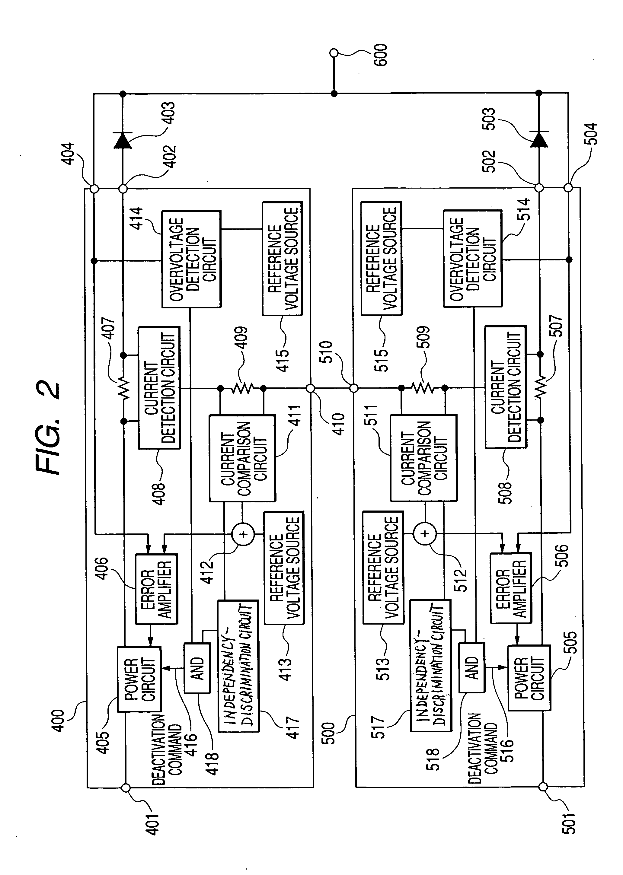
[0041] In the present second embodiment, an input of the overvoltage detection circuit 714 is connected to an anode of the OR diode 703. The overvoltage detection circuit 714 can also be connected to a cathode of the OR diode 703.
third embodiment
[0042]FIG. 4 shows the present invention, wherein a part of a power system, namely, a power source 800 is mainly shown. In FIG. 4, an input of a independency-discrimination circuit 817 is connected to a current comparison circuit 811 similarly to FIG. 2, whereas an output is connected to an addition circuit 819 which, as a connection circuit, adds a voltage to that of the reference voltage source 815 provided for an overvoltage detection circuit 814. The present embodiment is adapted such that when the independency-discrimination circuit 817 discriminates that an output voltage of the local power source is lower than that of the other (remote) power source, a voltage value for detecting an overvoltage is increased via the addition circuit in order for operation of the overvoltage detection circuit to change. Thus, an overvoltage detection circuit of the power source where an overvoltage failure has occurred operates first, hence preventing the other (normal) power source from being ...
first embodiment
[0044] In either embodiment, a detection voltage of the overvoltage detection circuit can be set to any voltage value. For example, if a permissible range of the voltage that a load circuit or the like requires is 75%, setting the detection voltage of the overvoltage detection circuit to 5% or less makes it possible for any changes in the output voltage of the power system to be controlled to 5% or less, even in the event of an overvoltage failure in either power source. This means that before or after or at the moment a power failure occurs, or in the course of the failure, or during the entire time from the occurrence of the failure, the power system can provide control for the output voltage to stay within its permissible fluctuation range and thus maintain the performance required. The electronic circuit (or the like) used as the load, therefore, can continue to operate without malfunctioning. The reliability improvement obtained in this power system is also the same as that of ...
PUM
 Abstract
Description
Claims
Application Information