Power supply device, vehicle in which same is used, and bus bar

Active Publication Date: 2021-07-01
SANYO ELECTRIC CO LTD
View PDF0 Cites 7 Cited by
  • Summary
  • Abstract
  • Description
  • Claims
  • Application Information

AI Technical Summary

Benefits of technology

The present invention provides a power supply device which includes multiple battery cells and a bus bar for connecting the electrode terminals of adjacent cells. The bus bar has at least three bending portions that allow for displacement absorption during battery cell movement without compromising the electrical connection. The second intermediate portion has a larger area than the first and may have a connecting cutout for connecting terminals. The bus bar may be made of different metals and has a strong joining strength with the same metal contact. The bus bar also has thin areas for reducing weight and thickness. These technical features improve the reliability and performance of the power supply device.

Problems solved by technology

Further, in a case where the power supply device receives outer force, it happens that the battery cells adjacently disposed are relatively misaligned.
In this shape, in a case where size between terminals of adjacent cells is short, there is a problem that forming the bus bar (press working) becomes difficult.
However, there is a problem that the bus bar made of the clad material is expensive.

Method used


Image

  • Power supply device, vehicle in which same is used, and bus bar
  • Power supply device, vehicle in which same is used, and bus bar
  • Power supply device, vehicle in which same is used, and bus bar

Examples


Embodiment Construction

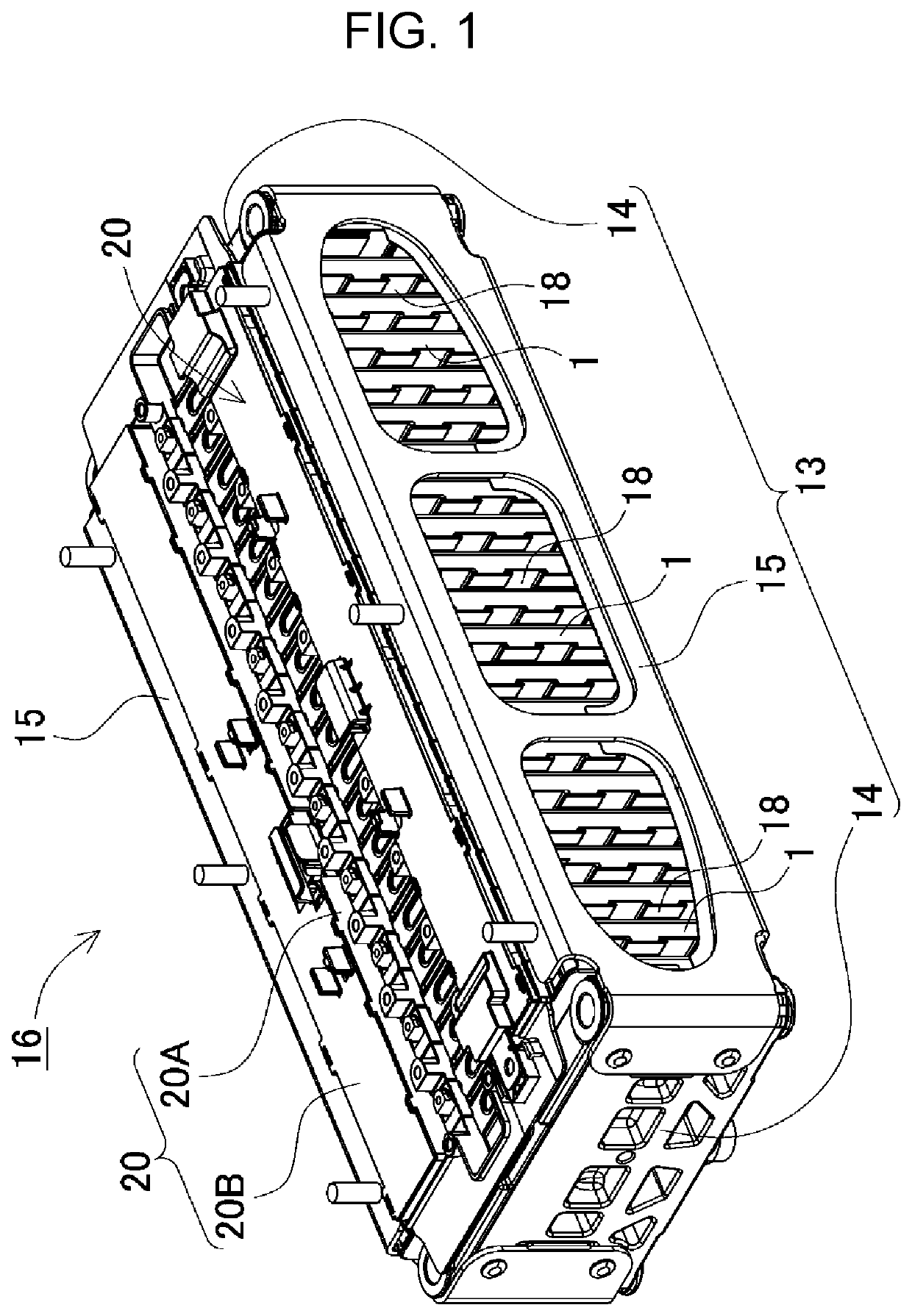
[0041]An exemplary embodiment of the present invention is described below with reference to the drawings. However, the exemplary embodiment described below shows an example of the present invention, and the battery pack of the present invention is not limited to the following. Further, in the present description, components shown in the scope of claims are not limited to the components of the exemplary embodiment. Furthermore, in the following description, the same names or the same reference marks denote the same components or same type components, and detailed description is appropriately omitted. Further, regarding the elements constituting the present invention, a plurality of elements may be formed of the same component, and one component may serve as the plurality of elements. To the contrary, the function of one component may be shared by the plurality of components.

[0042]The power supply device of the present invention is used for various purposes, such as a power supply mou...


PUM


Abstract

A plurality of battery cells each having a positive electrode terminal and a negative electrode terminal; and a bus bar which connects the electrode terminals facing each other in the battery cells adjacently disposed among the plurality of battery cells.

Description

TECHNICAL FIELD[0001]The present invention relates to a power supply device, a vehicle using the same, and a bus bar for electrically connecting battery cells used in the power supply device.BACKGROUND ART[0002]A power supply device using a secondary battery has been used for a power supply for driving a vehicle, for example. The power supply device mentioned above is provided with a plurality of battery cells 501, a plurality of insulating separators 518, a pair of bind bars 515, and a pair of end plates 514, as illustrated in an exploded perspective view in FIG. 5. Each of insulating separators 518 is interposed between adjacent battery cells 501. Battery cells 501 and insulating separators 518 are stacked in an alternating fashion to form battery stacked body 599. Both end faces of battery stacked body 599 in the stacking direction of battery cells 501 are respectively covered by end plates 514. Respective bind bars 515 extend along the stacking direction of battery cells 501, an...

Claims


Application Information

Patent Timeline
IPC IPC(8): H01M50/505H01M50/249H01M50/562H01M50/209H01M50/176H01M50/50H01M50/55H01M50/553
CPCH01M50/505H01M50/209H01M50/562H01M50/249H01M2220/20H01M50/264H01M50/278H01M50/503H01M50/516H01M50/514H01M50/553H01M50/522H01M50/572H01M50/528H01M50/50H01M50/55H01M50/176H01M50/507H01M50/561
Inventor OKADA, WATARUOTA, SHINJIUETA, YOSHIAKI
Owner SANYO ELECTRIC CO LTD
Why Eureka
Try Eureka