Multicarrier communication method and system, and communication apparatus incorporated therein

a communication method and multi-carrier technology, applied in the field of multi-carrier communication methods, can solve problems such as transmission power leakage or unwanted radiated emission, increase possibility, and increase the possibility of transmission/receiving non-correctable errors in data, so as to suppress unwanted radiated emission and increase the multi-value

Active Publication Date: 2005-04-14
PANASONIC CORP
View PDF20 Cites 15 Cited by
  • Summary
  • Abstract
  • Description
  • Claims
  • Application Information

AI Technical Summary

Benefits of technology

[0021] In view of the above, an object of the present invention is to provide a multicarrier communication method and system and an art related thereto, in which the multicarrier communication method and system is operable, in multicarrier communication using a balanced. transmission line such as a power line, to select a greater number of carriers and a greater number of modulation methods having greater multivalues, and to suppress unwanted radiated emission, in light of an SN-ratio and balancing of the transmission line.

Problems solved by technology

Assuming that each of the carriers C1, C2, and C3 employs the 16QAM-modulation method, there is an increased possibility that non-correctable errors in data might occur because of an insufficient SN-ratio of each of these carriers.
However, the PLC has particularity in which indoor power lines are used as transmission lines, and consequently has a problem of transmission power leakage or unwanted radiated emission caused by the above particularity.
This is a more serious issue to a high-frequency band PLC that is expected to evolve in the future.

Method used


Image

  • Multicarrier communication method and system, and communication apparatus incorporated therein
  • Multicarrier communication method and system, and communication apparatus incorporated therein
  • Multicarrier communication method and system, and communication apparatus incorporated therein

Examples


first embodiment

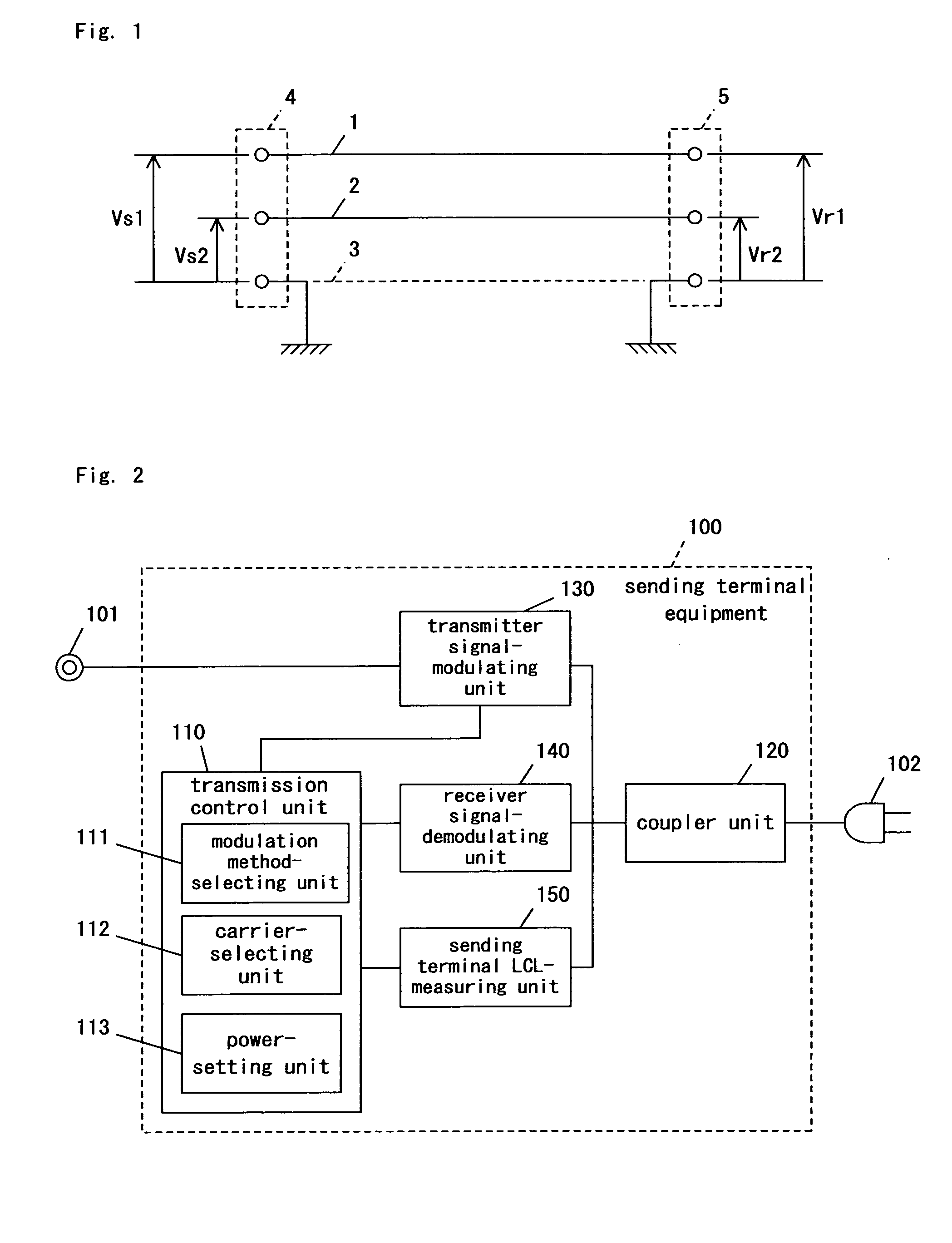
[0108]FIG. 2 is a block diagram illustrating sending terminal equipment 100 according to a first embodiment of the present invention.

[0109] The sending terminal equipment 100 for a multicarrier communication system according to the present embodiment includes a transmission control unit 110, a transmitter signal-modulating unit 130, a receiver signal-demodulating unit 140, a sending terminal LCL-measuring unit150, and a coupler unit 120. The transmission control unit 110 includes a modulation method-selecting unit 111, a carrier-selecting unit 112, and a power-setting unit 113.

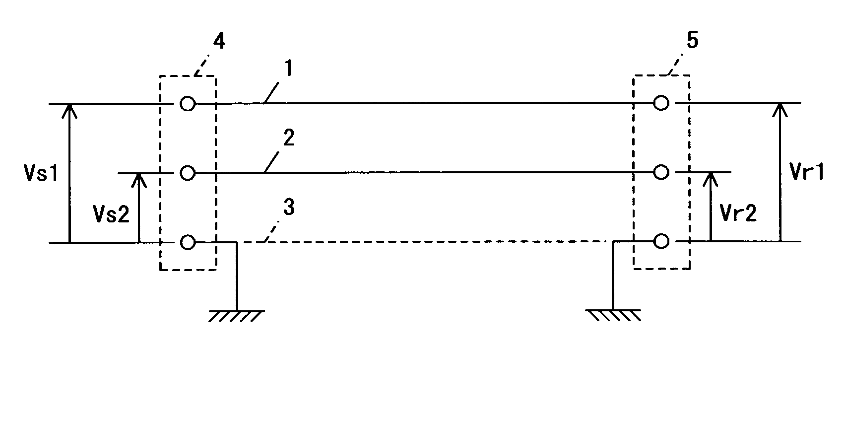
[0110] The coupler unit 120 connects the transmitter signal-modulating unit 130, receiver signal-demodulating unit 140, and sending terminal LCL-measuring unit 150 to a power line outlet (the first and second power lines 1, 2 at the sending terminal 4 in FIG. 1) through a plug 102.

[0111] The transmission control unit 110 is connected to the transmitter signal-modulating unit 130, the receiver signal-demodul...

second embodiment

[0136] Sending terminal equipment 100 and receiving terminal equipment 200 according to a second embodiment are the same as those of FIGS. 2 and 3. Therefore, the present embodiment is now described with reference to FIGS. 2 and 3.

[0137] An SN-ratio-measuring process according to the present embodiment is similar to that according to the previous embodiment, and descriptions related thereto are herein omitted.

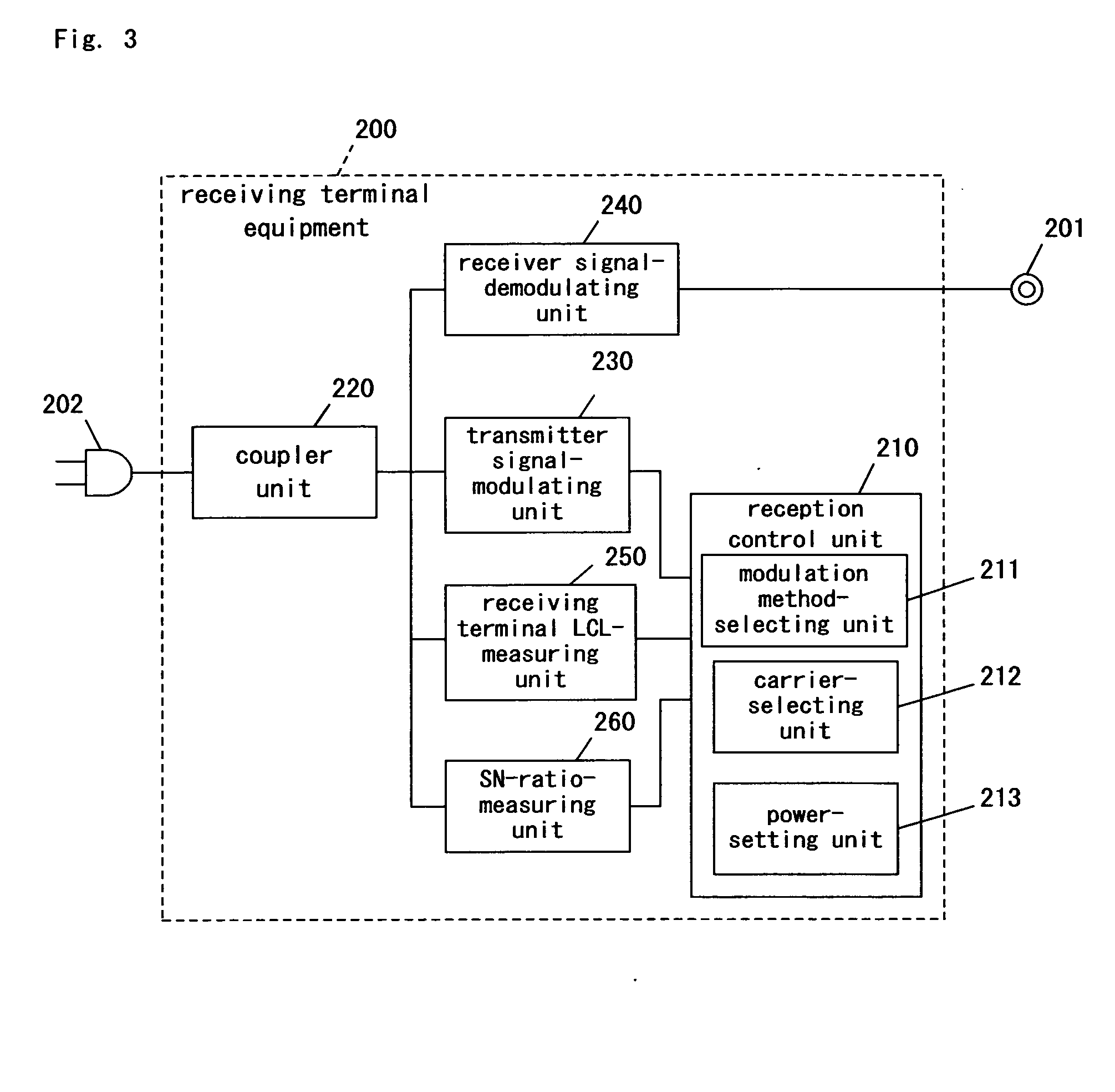
[0138] Pursuant to the present embodiment, the receiving terminal equipment 200 measures a balancing parameter LCL. More specifically, the receiving terminal LCL-measuring unit 250 measures, for each carrier, an LCL(r) defined by “Equation 2”, to provide an LCL(r) measurement value. The transmitter signal-modulating unit 230 transmits the LCL(r) measurement values to the sending terminal equipment 100 under the control of the reception control unit 210.

[0139] In the transmission control unit 110, the transmitted SN-ratio and LCL(r) measurement values of the carriers are used...

third embodiment

[0144] Sending terminal equipment 100 and receiving terminal equipment 200 according to a third embodiment are the same as those of FIGS. 2 and 3. Therefore, the present embodiment is now described with reference to FIGS. 2 and 3.

[0145] In the sending terminal equipment 100, the transmitter signal-modulating unit 130 transmits SN-ratio-measuring signals under the control of the transmission control unit 110. The SN-ratio-measuring signal may be the same as, e.g., the signal according to the first embodiment.

[0146] The SN-ratio-measuring signals are received by the receiving terminal equipment 200. Thereafter, the SN-ratio-measuring unit 260 measures an SN-ratio of each carrier to provide an SN-ratio measurement value. The SN-ratio measurement values are sent to the reception control unit 210.

[0147] The receiving terminal equipment 200 measures an LCL. More specifically, the receiving terminal LCL-measuring unit 250 measures, for each of the carriers, an LCL(r) defined by “Equatio...


PUM


Abstract

In a multicarrier communication using a balanced transmission line such as a power line, a multicarrier communication method operable to select carriers on the basis of an SN-ratio and balancing of the transmission line is provided. Available carriers are selected in accordance with the balancing of the balanced transmission line, in which the balancing is measured at either a sending terminal or a receiving terminal or alternatively at both of them, and the SN-ratio measured between the sending terminal and the receiving terminal. More specifically, any frequency domain having poor balancing and a poor SN-ratio is treated as a non-carrier-employing domain, and consequently the available carriers are selected at other frequency domains. In addition, a modulation method having the greatest permissible multivalue is selected for each of the carriers. The carriers are selected in light of the SN-ratio and balancing, or alternatively in highest-to-lowest order of frequency. Transmission power is controlled for each of the carriers to suppress radiated emission. The SN-ratio and balancing are measured at predetermined time intervals to renew the selection of the carriers and the selection of the modulation methods.

Description

BACKGROUND OF THE INVENTION [0001] 1. Field of the Invention [0002] The present invention relates to a multicarrier communication method and system using a balanced transmission line such as a power line, and a communication apparatus incorporated therein. [0003] 2. Description of the Related Art [0004] With the rapid evolution of intelligent home appliances, attention has been directed to power-line communications (hereinafter simply called a “PLC”) that allow existing power lines to be used as transmission lines, without wiring new cables, in order to control the intelligent home appliances in each household. [0005] In a wideband PLC system having expectation of its further development in the near future, a multicarrier system such as OFDM (Orthogonal Frequency Division Multiplexing) is predominantly employed as a PLC-modulating method. According to the multicarrier system, a so-called channel estimation method (a channel-evaluating method) has been developed to realize high-speed...

Claims


Application Information

Patent Timeline
Patent Type & Authority Applications(United States)
IPC IPC(8): H04B3/54H04L1/00H04L27/26
CPCH04B3/54H04B2203/5416H04L1/0003Y02B60/31H04L5/0046H04L5/006H04L25/028H04L5/0007Y02D30/50
Inventor WAKISAKA, TOSHIYUKIMAKI, MASAHIROKOGA, HISAOIGATA, YUJIICHIHARA, FUMIOYAMASHITA, AKIHIROHANADA, TSUNEHIROOISHI, MUTSUHIKO
Owner PANASONIC CORP
Why Eureka
Try Eureka