Needle assisted jet injector

a jet injector and needle technology, applied in the field of needle assisted jet injectors, can solve the problems of ineffectiveness of drugs that require a specific molecular structure arrangement, linear protein configuration, etc., and achieve the effect of preventing re-exposure of the needl

Inactive Publication Date: 2005-04-14
ANTARES PHARMA INC
View PDF11 Cites 80 Cited by
  • Summary
  • Abstract
  • Description
  • Claims
  • Application Information

AI Technical Summary

Benefits of technology

[0014] Retraction of the needle guard from the protecting position to the injecting position may activate the force generating source, which provides sufficient force to eject an amount of about 1 to 2 ml of the medicament in less than about 2.5 seconds. The jet injector can also include a locking element associated with the needle guard for locking the needle guard in the protecting position after activation of the injection device and after return of the needle guard to the protecting position, to prevent re-exposure of the needle.

Problems solved by technology

For example, drugs that require a specific molecular structural arrangement, such as a linear protein configuration, may be rendered ineffective due to shear forces caused by the delivery of the drug at high pressures that alter the structural arrangement of the drug.
Moreover, the lower pressure would make jet injection compatible with medicament stored and delivered in glass ampules, which typically cannot withstand the pressure typically reached by jet injectors.
As none of these devices involves delivery of the medicament using jet injection, the medicament delivery location is limited by the length of the needle.
Furthermore, as auto-injectors operate like syringes, the injection time is several seconds or longer.
The extended needle could lead to potential biohazards and safety concerns, such as accidental injections and spreading of diseases.
Also, the gas powered plunger is both complicated and expensive to manufacture.
However, this publication does not teach one the details of the driving mechanism necessary to practice the concept.
This relatively long injection time may create discomfort in the patient receiving the injection.
Also, the needle may move during the lengthy injection and add to the patients discomfort.

Method used


Image

  • Needle assisted jet injector
  • Needle assisted jet injector
  • Needle assisted jet injector

Examples


Embodiment Construction

[0055] For convenience, the same or equivalent elements of the invention of embodiments illustrated in the drawings have been identified with the same reference numerals. Further, in the description that follows, any reference to either orientation or direction is intended primarily for the convenience of description and is not intended in any way to limit the scope of the present invention thereto.

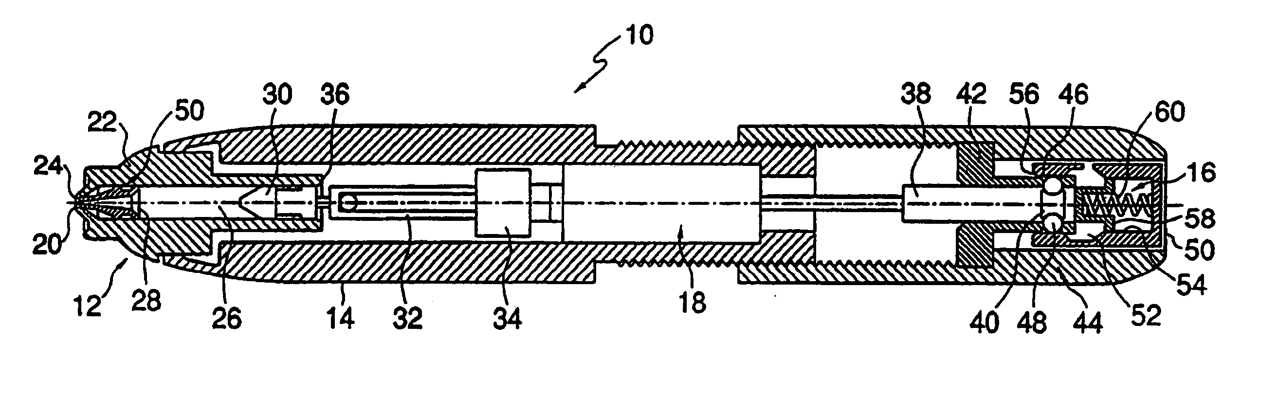
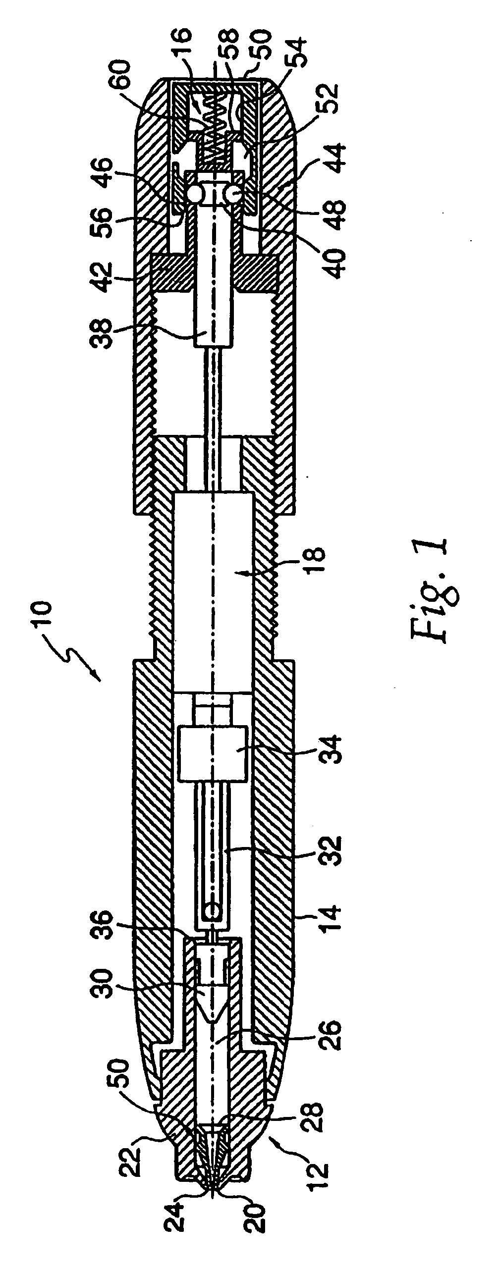
[0056] As shown in FIG. 1, a jet injector 10 according to the present invention comprises a nozzle assembly 12 attached to a housing 14. As used in this application, the term distal shall designate the end or direction toward the front of jet injector 10. The term proximal shall designate the end or direction toward the rear of the injector. The term longitudinal designates an axis connecting nozzle assembly 12 to jet injector 10, and the term transverse designates a direction substantially perpendicular to the longitudinal direction including arcs along the surface of jet injector 10, o...


PUM


Abstract

A jet injection device with a fluid chamber in a housing member for holding about 0.02 ml to about 3 ml of a medicament. An injection-assisting needle has an injection end that extends from the housing for inserting into a patient to a depth of up to about 5 mm. A force-generating source is configured to apply a pressure reaching about 100-1000 psi to the medicament in the chamber to expel the medicament through the injecting end of the needle.

Description

CROSS-REFERENCE TO RELATED APPLICATIONS [0001] This application is a division of co-pending U.S. application Ser. No. 10 / 861,420, filed Jun. 7, 2004, which is a division of U.S. application Ser. No. 09 / 779,603, filed Feb. 9, 2001, now U.S. Pat. No. 6,746,429, which is a continuation of International Patent Application No. PCT / US99 / 17946, filed Aug. 10, 1999, which claims priority to U.S. Provisional Application No. 60 / 096,464, filed on Aug. 11, 1998. The entire content of these applications is expressly incorporated herein by reference thereto.FIELD OF THE INVENTION [0002] The present invention is directed to a device for delivery of medicament, and in particular to a jet injector with a short needle to reduce the pressure at which the jet injector must eject the medicament for proper delivery. BACKGROUND OF THE INVENTION [0003] A wide variety of needleless injectors are known in the art. Examples of such injectors include those described in U.S. Pat. No. 5,599,302 issued to Lilley ...

Claims


Application Information

Patent Timeline
Patent Type & Authority Applications(United States)
IPC IPC(8): A61M5/00A61M5/20A61M5/24A61M5/28A61M5/30A61M5/32A61M5/34
CPCA61M5/002A61M2205/583A61M5/24A61M5/2425A61M5/2466A61M5/282A61M5/288A61M5/30A61M5/3202A61M5/3232A61M5/3243A61M5/326A61M5/3286A61M5/349A61M2005/3247A61M5/20
Inventor SADOWSKI, PETER L.DEBOER, DAVID M.BERMAN, CLAUDE L.LESCH, PAUL R. JR.HOLLAND, MARGARET L.
Owner ANTARES PHARMA INC
Why Eureka
Try Eureka