Winding device

A winding device and package technology, applied in the directions of transportation and packaging, delivery of filamentous materials, and thin material processing, etc., can solve the problems of deterioration of spinning quality, difficult lifting mechanism, and large operating cost burden, so as to prevent further Contact, simple structure, anti-friction effect

Active Publication Date: 2017-04-12
MURATA MASCH LTD
View PDF4 Cites 0 Cited by
  • Summary
  • Abstract
  • Description
  • Claims
  • Application Information

AI Technical Summary

Problems solved by technology

In the winding device with such a structure, since the moment of inertia such as the outer diameter of the package changes, it is difficult to use the regenerative power obtained from the rotation of the package as the power source of the lifting mechanism.
That is, when the moment of inertia of the package is small in the state where the yarn is almost not wound, regenerative power cannot be stably obtained, so the energization to the solenoid valve and the like cannot be continued.
Therefore, even if the winding device with such a structure separates the package from the roll, it cannot maintain the separated state, and there is a problem that the package and the roll come into contact again.
That is, there is a problem that the spun yarn wound on the package is rubbed by the rotation of the roller, and the quality of the spun yarn is deteriorated.
[0007] Also, even in a winding device with a structure in which the package is driven to rotate by the actively rotating roller, the same problem is considered to occur when the moment of inertia of the roller is small.
That is, when the moment of inertia of the roller is small, since regenerative power cannot be obtained stably, it is not possible to continuously energize the solenoid valve, etc.
In addition, if the energization to the solenoid valve stops due to a power failure, the package is separated from the roller by the force of the spring (the structure using a normally open solenoid valve). ), the power used to make the package and the roller contact is always consumed, so the burden on the running cost is large

Method used


Image

  • Winding device
  • Winding device
  • Winding device

Examples


Embodiment Construction

[0034] First, a winding device 100 according to an embodiment of the present invention will be described.

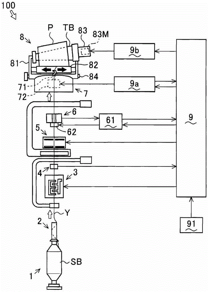
[0035] figure 1 It is a figure which shows the whole structure of the winding apparatus 100. The hollow arrow in the figure indicates the conveying direction of the spun yarn Y. In addition, arrows filled in black in the figure indicate the movable direction of a member (the traverse guide 71 ) constituting the winding device 100 .

[0036] The winding device 100 includes a yarn supplying unit 1 . The yarn supplying bobbin SB on which the spun yarn (yarn) Y is wound is mounted in the yarn supplying section 1 . The winding device 100 includes a yarn unwinding auxiliary section 2, a tension applying section 3, a tension detecting section 4, a splicing section 5, and a defect detecting section 6 along the conveying direction of the spun yarn Y unwound from the yarn supplying bobbin SB. , Traversing portion 7 and winding portion 8 . Furthermore, the winding device 100 i...


PUM


Abstract

The present invention provides a winding device capable of maintaining a state in which a package is separated from a roll without using regenerative power. It is provided with a cradle (81) that rotatably supports a package (P), and rotates to assist winding of the spun yarn (Y) while in contact with the package (P) (contact roller 82 ), and the winding device (100) of the lifting mechanism (Rm) that rotates the above-mentioned cradle (81) so that the above-mentioned package (P) is in contact with the above-mentioned roller (touch roller 82) or in a separated state of separation , the above-mentioned elevating mechanism (Rm) has a locking function for maintaining the above-mentioned states without power supply.

Description

technical field [0001] The present invention relates to the technology of a winding device for forming a package by winding spinning. Background technique [0002] Conventionally, a winding device is known that winds spun yarn unwound from a yarn supplying bobbin to form a package (see, for example, JP-A-2009-286608). The winding device includes a cradle that rotatably supports the package, and a roller that rotates while in contact with the package to assist winding of the spun yarn. In addition, the winding device is provided with an elevating mechanism that rotates the cradle so that the package and the roller can contact or separate from each other (see, for example, JP-A-2010-13259). [0003] The winding device cuts off the spun yarn and separates the package from the roll in the event of a power failure. This is for the purpose of preventing the spun yarn having a defective part from being wound into the package, and at the same time preventing the deterioration of t...

Claims


Application Information

Patent Timeline
Patent Type & Authority Patents(China)
IPC IPC(8): B65H54/70
CPCB65H54/44B65H63/0364B65H2701/31
Inventor 谷川保伸
Owner MURATA MASCH LTD
Why Eureka
Try Eureka