Lumber rule apparatus

Inactive Publication Date: 2005-04-21
MILLER JOHN H JR
View PDF17 Cites 3 Cited by
  • Summary
  • Abstract
  • Description
  • Claims
  • Application Information

AI Technical Summary

Benefits of technology

[0019] It is another object of the present invention to provide a new and improved lumber rule apparatus which may be easily and efficiently manufactured and marketed.
[0020] It is a further object of the present invention to provide a new and improved lumber rule apparatus which is of durable and reliable construction.
[0021] An even further object of the present invention is to provide a new and improved lumber rule apparatus which is susceptible of a low cost of manufacture with regard to both materials and labor, and which accordingly is then susceptible of low prices of sale to the consuming public, thereby making such lumber rule apparatus available to the buying public.
[0023] Still another object of the present invention is to provide a new and improved lumber rule apparatus that provides a separable unit which includes the gauging members and which can be replaced if the gauging members are damaged or broken.
[0024] Yet another object of the present invention is to provide a new and improved lumber rule apparatus which permits a user to free one's hands from the lumber gauge and then to resume gauging operations.

Problems solved by technology

There are times, however, when some lumber may be somewhat out of reach from the person trying to gauge the lumber.
When the lumber is out of reach from the person trying to gauge the lumber, the devices in the patents cited above cannot be readily used.
With a conventional lumber gauge, if the gauging members are damaged or broken, the entire lumber gauge will have to be replaced.
The conventional lumber gauges do not have features that provide for this freeing of one's hands followed by a resumption of gauging operations.

Method used


Image

  • Lumber rule apparatus
  • Lumber rule apparatus
  • Lumber rule apparatus

Examples


Embodiment Construction

[0035] With reference to the drawings, a new and improved lumber rule apparatus embodying the principles and concepts of the present invention will be described.

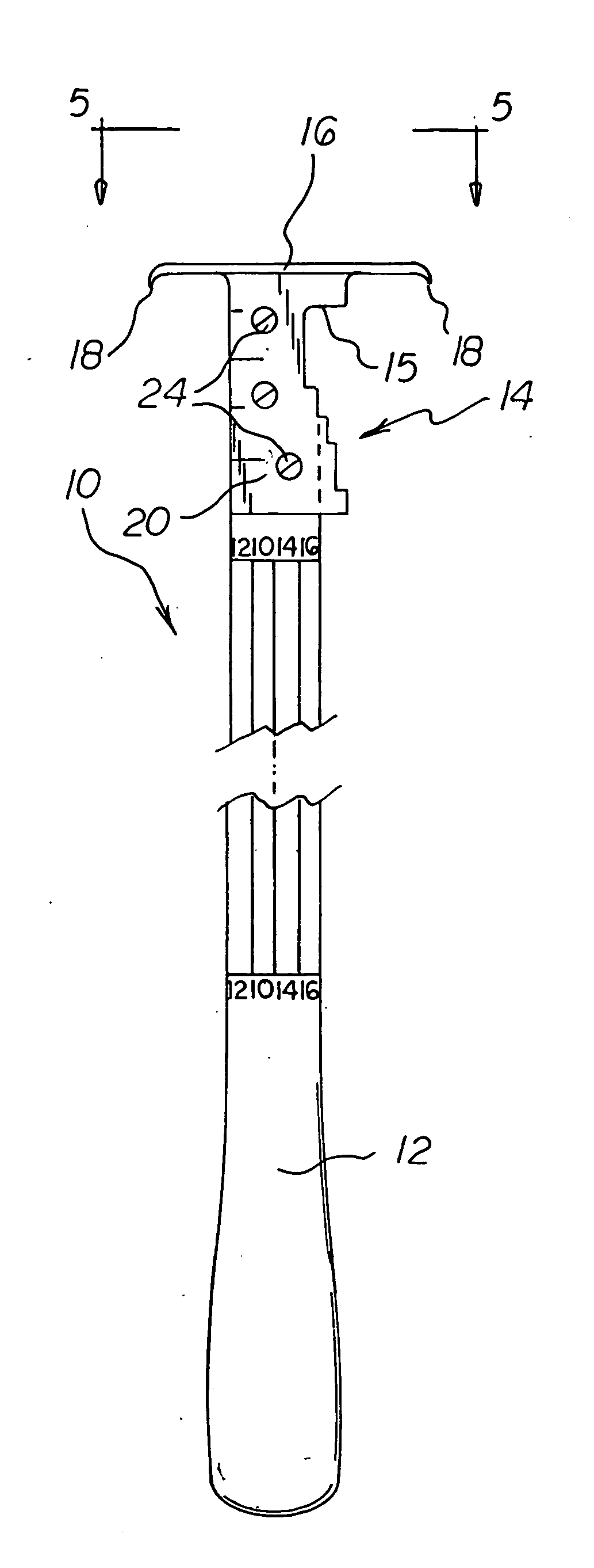
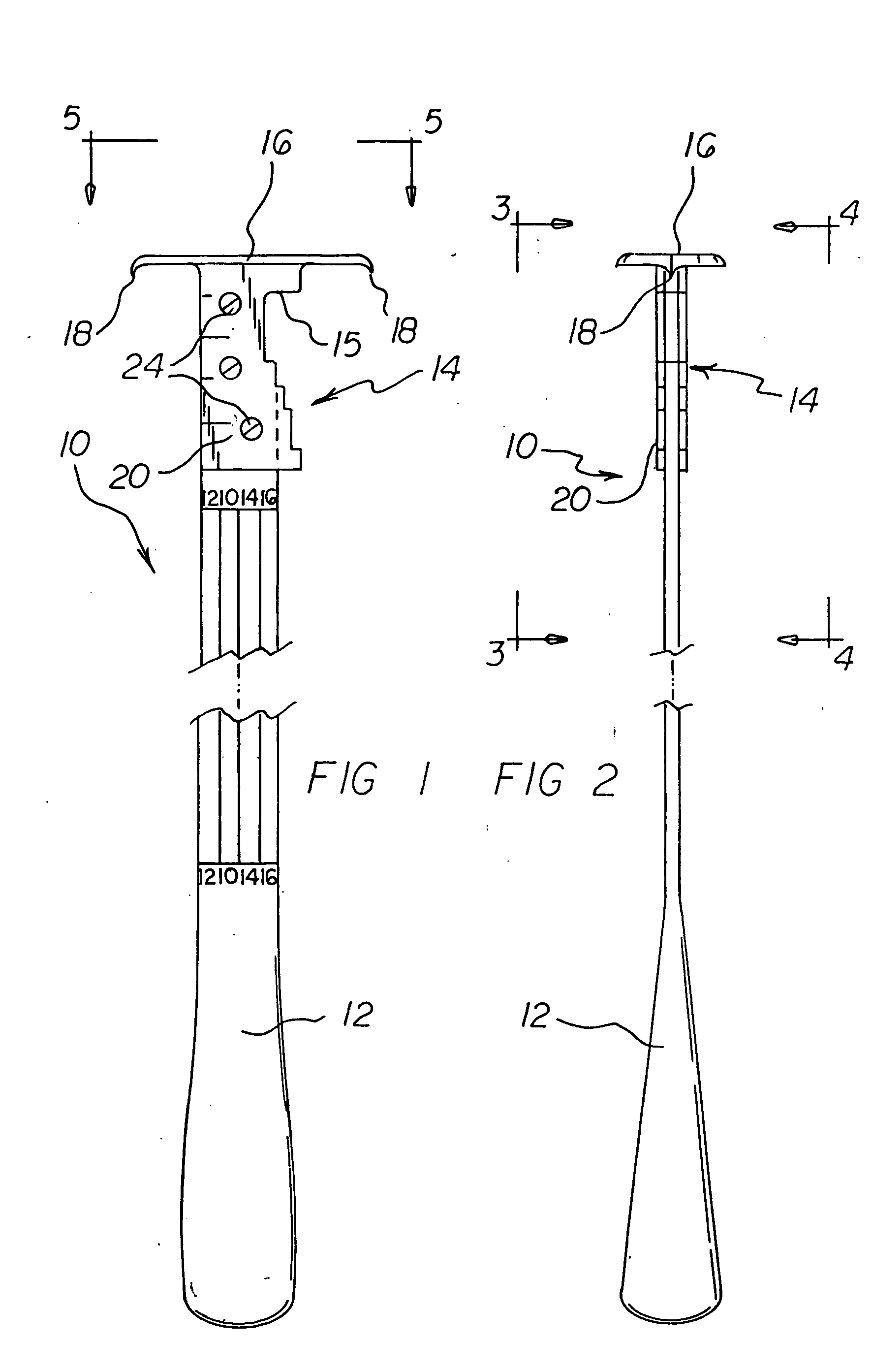
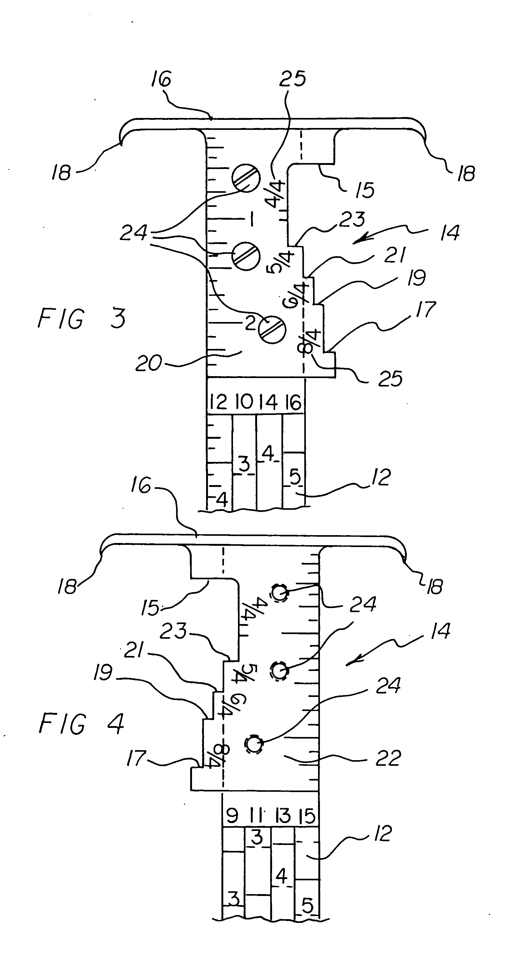
[0036] Turning to FIGS. 1-5, there is shown a first embodiment of the lumber rule apparatus of the invention generally designated by reference numeral 10. In the first embodiment, lumber rule apparatus 10 includes a gauge head 14 which includes first fastener reception channels 26, a handle 12 which includes second fastener reception channels 28, and fasteners 24 received in the first fastener reception channels 26 and the second fastener reception channels 28 for securing the gauge head 14 to the handle 12. In this respect, the gauge head 14 is detachable from the handle 12 by removing the set screws 24.

[0037] The gauge head 14 includes a primary gauge surface 15, a plurality of secondary gauge surfaces spaced apart from the primary gauge surface 15, and a suspension member located proximal to the primary gauge surface 15...


PUM


Abstract

A lumber rule apparatus includes a gauge head which includes first fastener reception channels, a handle which includes second fastener reception channels, and fasteners received in the first fastener reception channels and the second fastener reception channels for securing the gauge head to the handle. In this respect, the gauge head is detachable from the handle by removing the set screws. The gauge head includes a primary gauge surface, a plurality of secondary gauge surfaces spaced apart from the primary gauge surface, and a suspension member located proximal to the primary gauge surface and distal to the secondary gauge surfaces. The gauge head includes indicia for indicating lumber sizes for grading lumber. The suspension member can be a two-ended suspension member. The two-ended suspension member includes downwardly extending lumber spikes. The apparatus is used for grading lumber.

Description

CROSS-REFERENCE TO RELATED APPLICATION [0001] This application claims priority based upon my copending Provisional Application Ser. No. 60 / 512,019; filed on or about Oct. 20, 2003.BACKGROUND OF THE INVENTION [0002] 1. Field of the Invention [0003] The present invention relates generally to gauges, and, more particularly, to gauges especially adapted for gauging the thickness of lumber. [0004] 2. Description of the Prior Art [0005] The need to gauge the thickness of lumber is well known. Also, the desirability of having a hand-held gauge for lumber is well known. In this respect, throughout the years, a number of innovations have been developed relating to hand-held lumber gauges; and the following U.S. patents are representative of some of those innovations: U.S. Pat. Nos. 489,584, 4,584,774, 6,434,852, Des. 256,564, and Des. 308,831. [0006] All of the patents cited above share a common conventional characteristic. In use, they are hand-held adjacent to easily reached lumber that is...

Claims


Application Information

Patent Timeline
IPC IPC(8): G01B3/30G01C3/10
CPCG01B3/30
Inventor MILLER, JOHN H. JR.
Owner MILLER JOHN H JR
Why Eureka
Try Eureka