Lysimeter apparatus

a lysimeter and apparatus technology, applied in the direction of testing water, instruments, borehole/well accessories, etc., can solve the problems of limited usefulness, high undesirable excavation or drilling, and inability to install prior lysimeters

Inactive Publication Date: 2005-04-21
BATTELLE ENERGY ALLIANCE LLC
View PDF7 Cites 2 Cited by
  • Summary
  • Abstract
  • Description
  • Claims
  • Application Information

AI Technical Summary

Problems solved by technology

Although prior lysimeters have been useful in gathering much information, such lysimeters have several shortcomings which have limited their usefulness.
For example, prior lysimeters cannot be installed without prior excavation or drilling, and in contaminated areas such excavation or drilling is highly undesirable as it would tend to spread contamination.
Additionally, such lysimeters have provided only small samples of subsurface liquids.
Another problem is that lysimeters are very fragile.
They are made of ceramic, tin, copper, plastics, or similar such materials and cannot be installed directly through difficult materials such as hardened soils, concrete, steel, other metals, or waste products.
However, as described above, placing probes into the subsurface for data collection in such sites has not been feasible, because the placing of such probes would require drilling or coring which would bring contaminated “cuttings” to the surface and would create a pathway through which contaminated emissions may escape.
Unfortunately, such probe placement only provides information when the contaminants have already migrated outside of the waste disposal site area.
Moreover, at the point when the contaminants have already migrated outside of the waste disposal site area, it is likely that a major contaminant plume already exists in the subsurface soil and aquifer making remediation and containment efforts much more difficult and costly.

Method used


Image

  • Lysimeter apparatus
  • Lysimeter apparatus
  • Lysimeter apparatus

Examples


Embodiment Construction

[0015] This disclosure of the invention is submitted in furtherance of the constitutional purposes of the U.S. Patent Laws “to promote the progress of science and useful arts” (Article 1, Section 8).

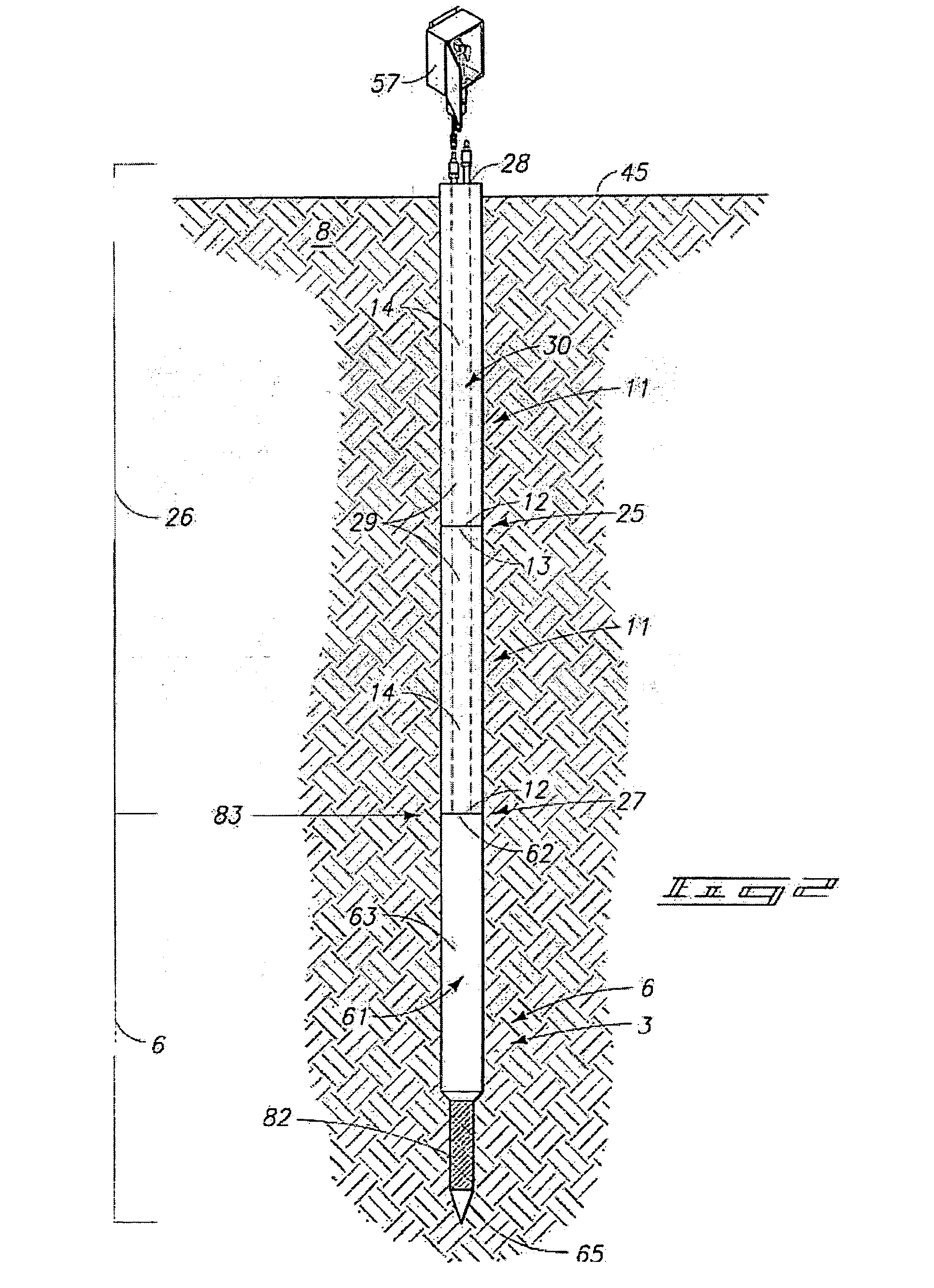
[0016] The invention relates to methods and apparatus for subsurface testing. More specifically, the invention relates to methods and apparatus for sampling subsurface liquids from the substrate. One embodiment of the invention allows such sampling to be carried out in either contaminated or non-contaminated sites without the need for drilling, coring, or prior excavation. In one embodiment, a method includes placing the instrumented probe into the substrate using direct push, sonic drilling, or a combination of direct push and sonic drilling.

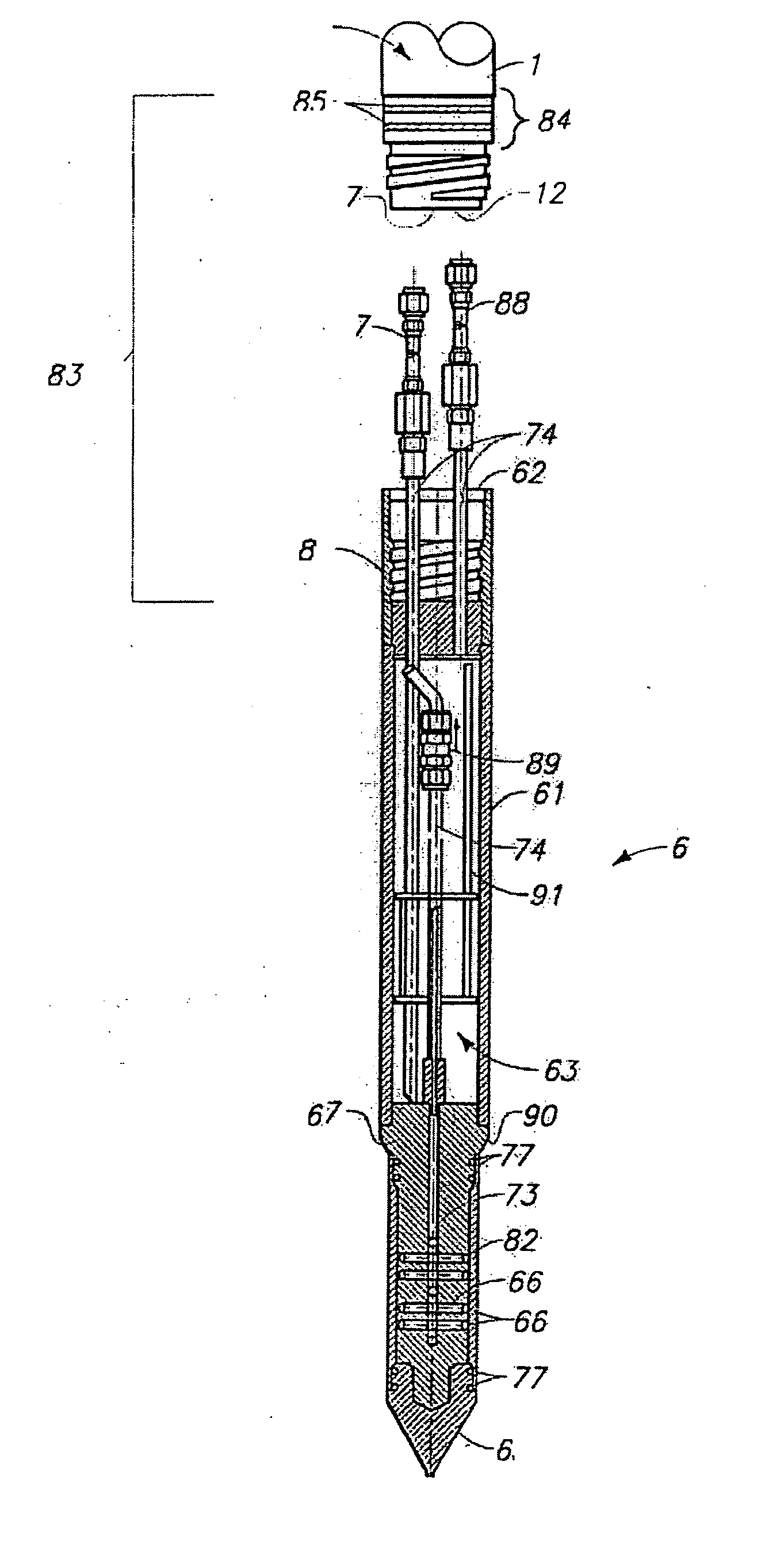
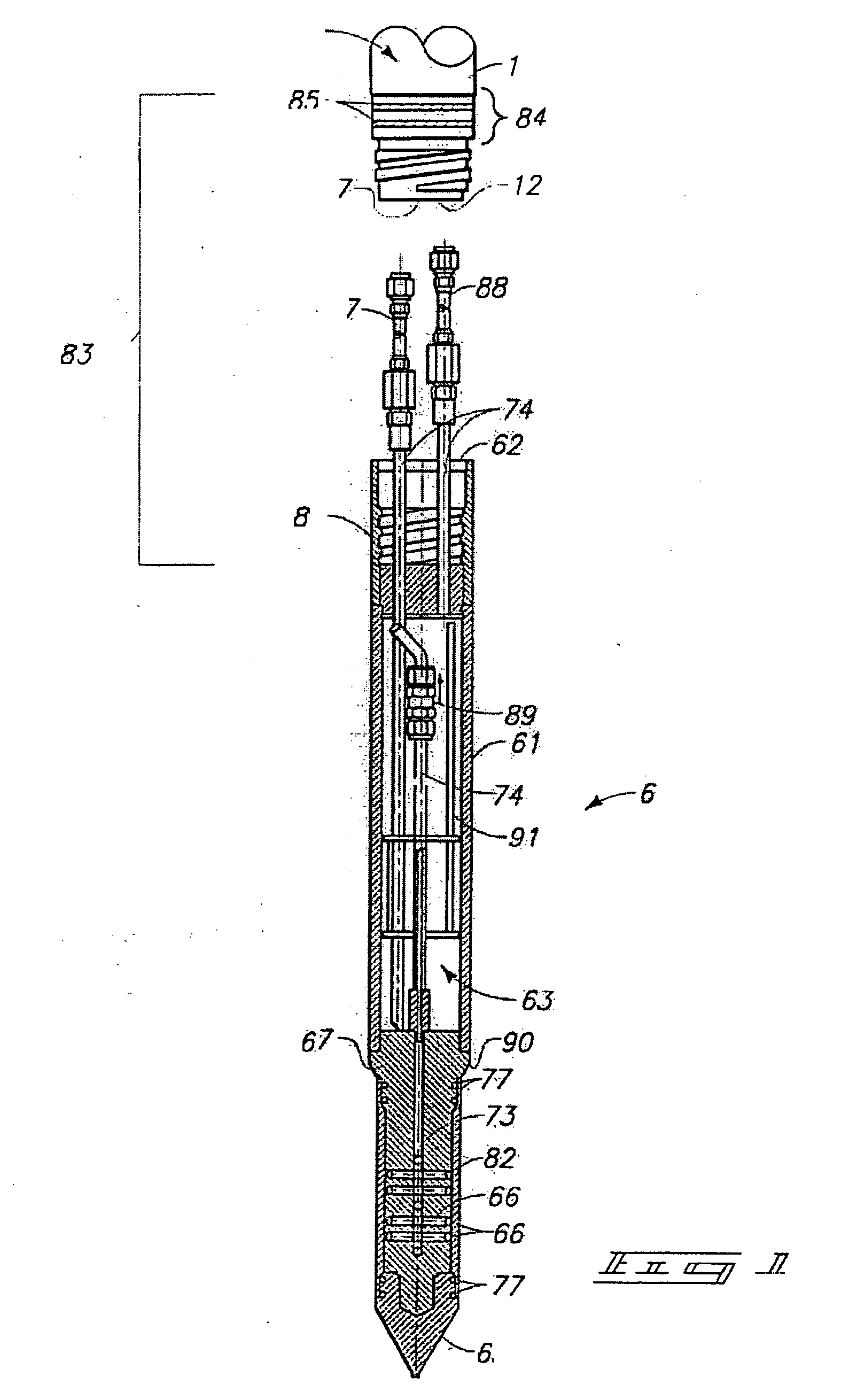
[0017]FIGS. 1 and 2 show a lysimeter 6 for sampling subsurface liquids. The lysimeter 6 includes a lysimeter casing 61. The lysimeter casing 61 includes a drive portion 62, a reservoir portion 63, and a tip portion 65. The tip portion 65 includes ...


PUM

PropertyMeasurementUnit
volumeaaaaaaaaaa
diameteraaaaaaaaaa
diameteraaaaaaaaaa

Abstract

A suction lysimeter for sampling subsurface liquids includes a lysimeter casing having a drive portion, a reservoir portion, and a tip portion, the tip portion including a membrane through which subsurface liquids may be sampled; a fluid conduit coupled in fluid flowing relation relative to the membrane, and which in operation facilitates the delivery of the sampled subsurface liquids from the membrane to the reservoir portion; and a plurality of tubes coupled in fluid flowing relation relative to the reservoir portion, the tubes in operation facilitating delivery of the sampled subsurface liquids from the reservoir portion for testing. A method of sampling subsurface liquids comprises using this lysimeter.

Description

RELATENT APPLICATIONS [0001] This application is a divisional of pending U.S. application Ser. No. 10 / 285,798, filed on Oct. 31, 2002.GOVERNMENT RIGHTS [0002] This invention was made with Government support under Contract DE-AC07-99ID13727 awarded by the U.S. Department of Energy. The Government has certain rights in the invention.TECHNICAL FIELD [0003] The invention relates to methods and apparatus for subsurface testing. More specifically the invention relates to methods and apparatus for sampling subsurface liquids. BACKGROUND OF THE INVENTION [0004] Water and associated contaminants seep into the ground and travel through a subsurface region known as the vadose zone (a region of unsaturated soil). How the water and associated contaminants move in the vadose zone, to a large degree, determines how much contamination (such as gasoline additives, agricultural chemicals, or buried waste leakage) may end up in a water supply (such as an aquifier). Therefore, gaining an understanding ...

Claims


Application Information

Patent Timeline
Patent Type & Authority Applications(United States)
IPC IPC(8): E02D1/06E21B49/08G01N1/14G01N33/18G01N33/24
CPCE02D1/06G01N33/246G01N1/14E21B49/084
Inventor CLARK, DON T.ERICKSON, EUGENE E.CASPER, WILLIAM L.EVERETT, DAVID M.HUBBELL, JOEL M.SISSON, JAMES B.
Owner BATTELLE ENERGY ALLIANCE LLC
Why Eureka
Try Eureka