Exhaust device

Inactive Publication Date: 2005-04-21
HONDA MOTOR CO LTD
View PDF13 Cites 17 Cited by
  • Summary
  • Abstract
  • Description
  • Claims
  • Application Information

AI Technical Summary

Benefits of technology

[0008] Accordingly, it is an object of the present invention to provide an exhaust device which makes it possible

Problems solved by technology

However, this exhaust device involves a problem in that the bulged portion must be formed in a large size.
Therefore, the designing of the vehicle body i

Method used


Image

  • Exhaust device
  • Exhaust device
  • Exhaust device

Examples


Example

[0052] Now, a first embodiment of the present invention will be described referring to the drawings.

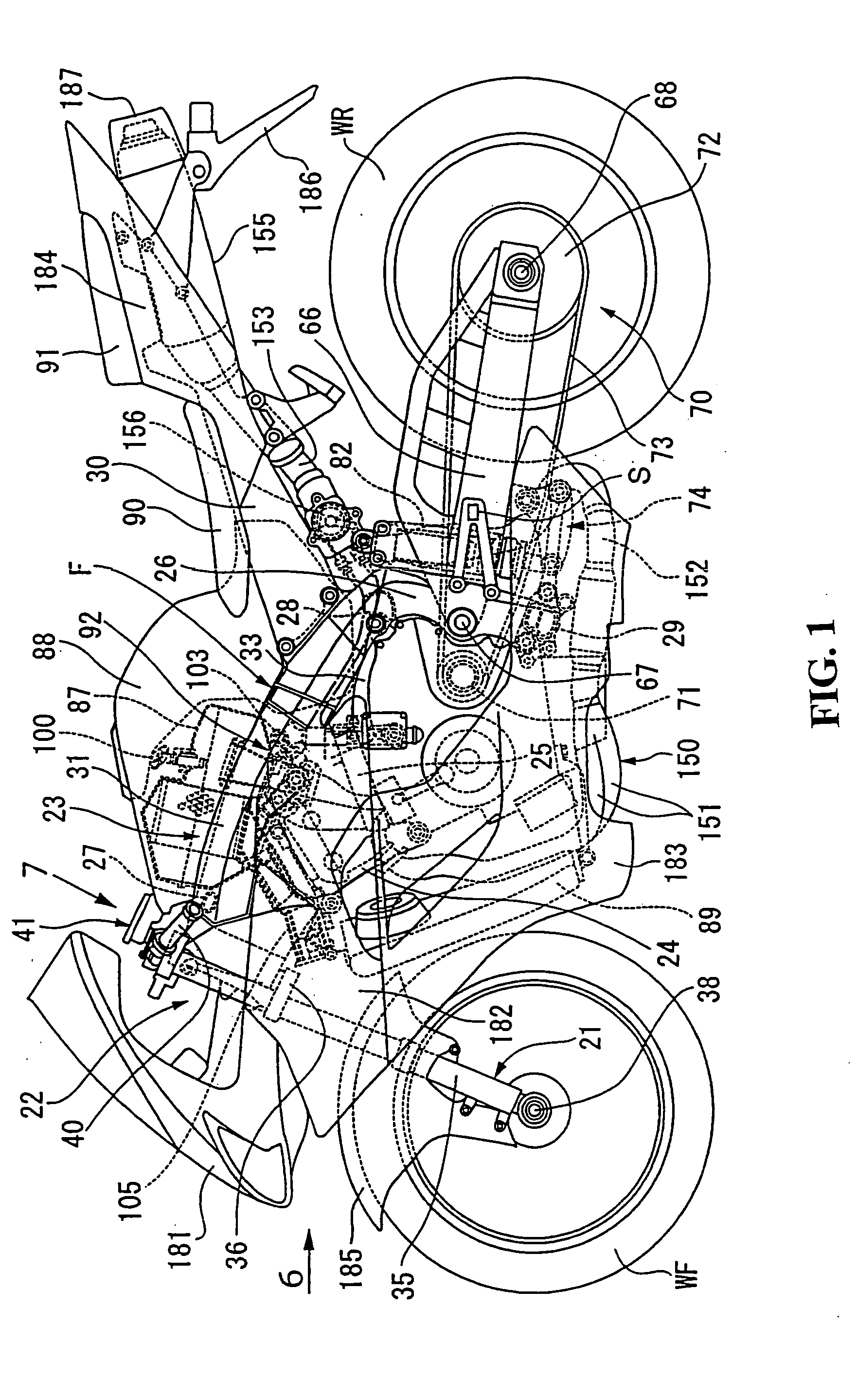
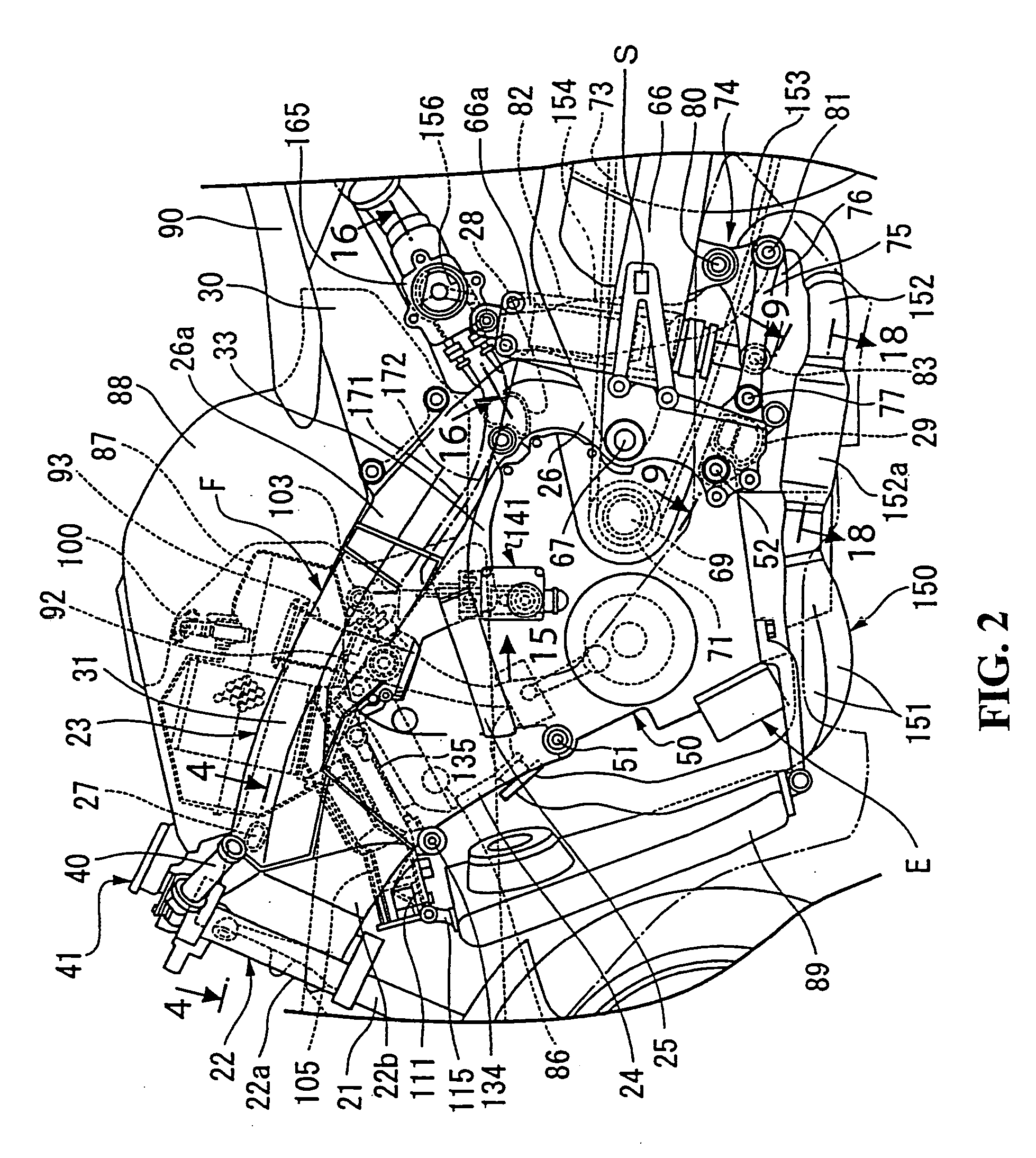
[0053] In FIGS. 1 to 3, a vehicle body frame F of the motorcycle includes a head pipe 22 for steerably supporting a front fork 21 for a shaft supporting a front wheel WF. A left-right pair of main frames 23 . . . extend rearwardly and downwardly from the head pipe 22 with a left-right pair of engine hangers 24 . . . welded to the head pipe 22 and front portions of both the main frames 23 . . . and extending downwardly from the main frames 23 . . . . Connection pipes 25 . . . are provided for connecting between support plate portions 33 . . . which are provided at lower portions of both the engine hangers 24 . . . and rear portions of the main frames 23 . . . . A left-right pair of pivot plates 26 . . . extend downwardly from rear portions of the main frames 23 . . . with a first cross pipe 27 bridgingly disposed between front portions of the main frames 23 . . . . A second cross pipe...


PUM

PropertyMeasurementUnit
Diameteraaaaaaaaaa
Widthaaaaaaaaaa
Surface areaaaaaaaaaaa

Abstract

To provide an exhaust device for enhancing the appearance quality, secure the degree of freedom in designing and enhance the cooling performance. An exhaust device in which a second exhaust muffler at a rear portion of an exhaust system extends rearwardly from an engine is disposed in a rear portion of a rear cowl wherein a rear end surface of the second exhaust muffler is covered with a resin-made muffler rear cover.

Description

CROSS-REFERENCE TO RELATED APPLICATIONS [0001] The present application claims priority under 35 USC 119 to Japanese Patent Application No. 2003-317444 filed on Sep. 9, 2003 the entire contents of which are hereby incorporated by reference. BACKGROUND OF THE INVENTION [0002] 1. Field of the Invention [0003] The present invention relates to an exhaust device for a vehicle, for example, a motorcycle. [0004] 2. Description of Background Art [0005] Conventionally, exhaust devices are known wherein a muffler positioned at a rear portion of an exhaust system extends rearwardly from an engine and is disposed in a rear cowl. In such exhaust devices the rear cowl may be provided with a bulged portion in the left-right direction. The bulged portion is provided with an air guide portion, while the rear cowl is provided with an air exhaust port at a rear portion thereof. In addition, the muffler is disposed along a cooling passage extending from the air guide port to the air exhaust port. See, f...

Claims


Application Information

Patent Timeline
IPC IPC(8): B62J23/00B62J99/00B62M7/02F01N13/08F01N13/20
CPCF01N13/005F01N13/08F01N2590/04F01N2340/04F01N2530/22F01N13/082
Inventor OKUNOSONO, TOSHIHIKO
Owner HONDA MOTOR CO LTD
Why Eureka
Try Eureka