

Liquid ejecting apparatus
- Summary
- Abstract
- Description
- Claims
- Application Information
AI Technical Summary
Benefits of technology
Problems solved by technology
Method used
Image

Examples
embodiment 1
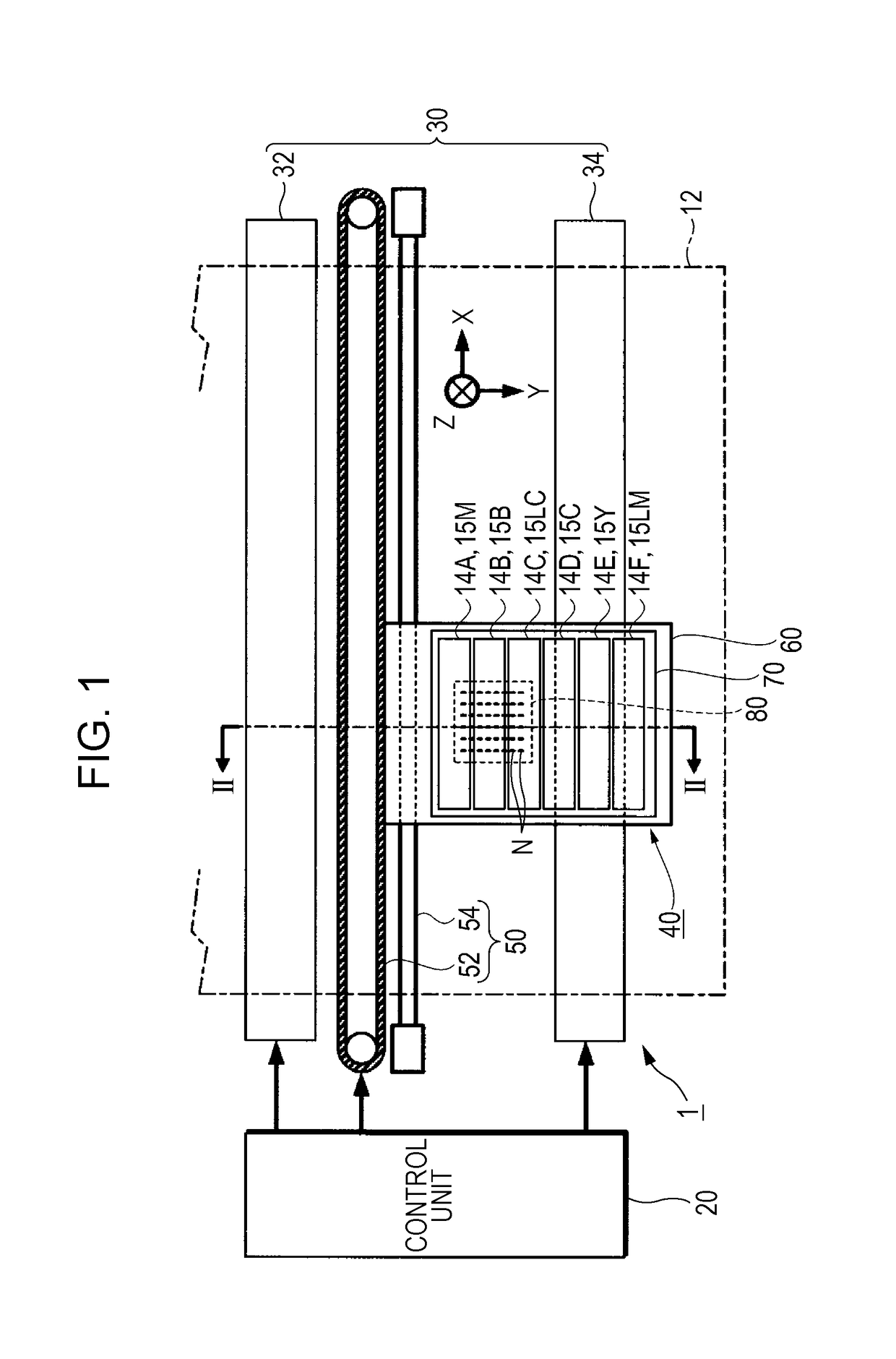
[0044]FIG. 1 is a configuration view of a liquid ejecting apparatus according to Embodiment 1.
[0045]A liquid ejecting apparatus 1 according to the present embodiment is an ink jet type printing apparatus that ejects an ink 15, which is one example of a “liquid”, onto a medium 12. A typical example of the medium 12 is printing paper, but it is also possible to use various media such as a fabric or a resin film.
[0046]As shown in FIG. 1, the liquid ejecting apparatus 1 is provided with a control unit 20, a transport mechanism 30, a liquid ejecting unit 40, and a movement mechanism 50. For example, the control unit 20 is configured to include a control device such as a central processing unit (CPU) and a storage circuit such as semiconductor memory (not illustrated in the drawings), and controls each component of the liquid ejecting apparatus 1 in an integral manner as a result of the control device executing a program stored in a storage circuit.
[0047]The transport mechanism 30 transpo...
embodiment 2
[0117]FIG. 5 is a view that corresponds to FIG. 1, and is a configuration view of a liquid ejecting apparatus according to Embodiment 2. FIG. 6 is a view that corresponds to FIG. 2, and is cross-sectional view along a line VI-VI in FIG. 5. FIG. 7 is a view that corresponds to FIG. 4, and is an exploded perspective view of a liquid ejecting unit.
[0118]Hereinafter, an outline of a liquid ejecting apparatus 1A according to the present embodiment will be described focusing on the differences from Embodiment 1 with reference to FIGS. 5 to 7. In addition, constituent sites that are the same as those of Embodiment 1 will be given the same reference numerals, and overlapping descriptions thereof will be omitted.
[0119]As shown in FIG. 5, five types (five colors) of ink 15 are used by the present embodiment and this is a difference from Embodiment 1. To explain in more detail, the ink 15 used in the present embodiment is configured by a photo black (PB) ink 15PB, a matte black (MB) ink 15MB, ...
embodiment 3
[0135]FIG. 8 is a view that corresponds to FIG. 1, and is a configuration view of a liquid ejecting apparatus according to Embodiment 3. FIG. 9 is a view that corresponds to FIG. 2, and is cross-sectional view along a line IX-IX in FIG. 8. FIG. 10 is a view that corresponds to FIG. 4, and is an exploded perspective view of a liquid ejecting unit. FIG. 11 is a schematic view of the main components of a valve unit. That is, FIG. 11 is a schematic view of a flow pressure adjustment portion 133 built into a valve unit 17.
[0136]Hereinafter, an outline of a liquid ejecting apparatus 1B according to the present embodiment will be described focusing on the differences from Embodiment 1 with reference to FIGS. 8 to 11. In addition, constituent sites that are the same as those of Embodiment 1 will be given the same reference numerals, and overlapping descriptions thereof will be omitted.
[0137]As shown in FIG. 8, the liquid ejecting apparatus 1B according to the present embodiment is an off-ca...
PUM
 Abstract
Description
Claims
Application Information