Positioning structure between parts of different materials, and assembly structure of motor

Inactive Publication Date: 2007-02-01
JAPAN SERVO CO LTD
View PDF5 Cites 9 Cited by
  • Summary
  • Abstract
  • Description
  • Claims
  • Application Information

AI Technical Summary

Benefits of technology

[0010] The present invention is accomplished in view of the problem in the prior art and a first object thereof is to provide a positioning structure between parts of different materials, which is

Problems solved by technology

However, the conventional positioning structure of a motor has a problem that environmental variation, such as temperature variation and humidity variation, changes the relative positional relationship between the front cover 1 and the stator assembly 2.
As a result, the rotor may contact the stator assembly 2 and rotation may become impossible.
Further, since the resin part deforms easily

Method used


Image

  • Positioning structure between parts of different materials, and assembly structure of motor
  • Positioning structure between parts of different materials, and assembly structure of motor
  • Positioning structure between parts of different materials, and assembly structure of motor

Examples


Example

First Embodiment

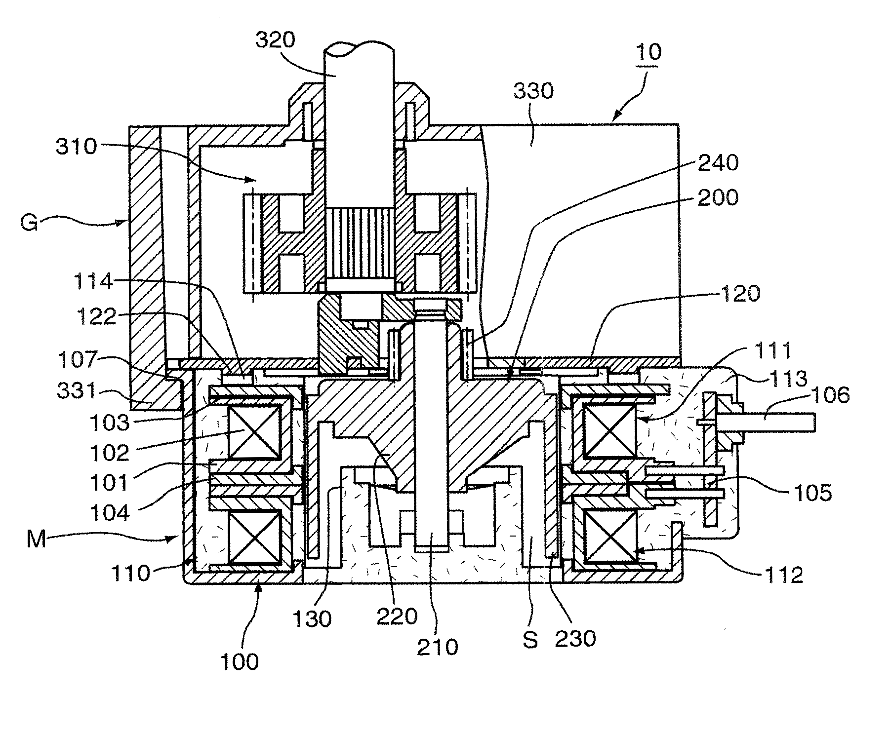
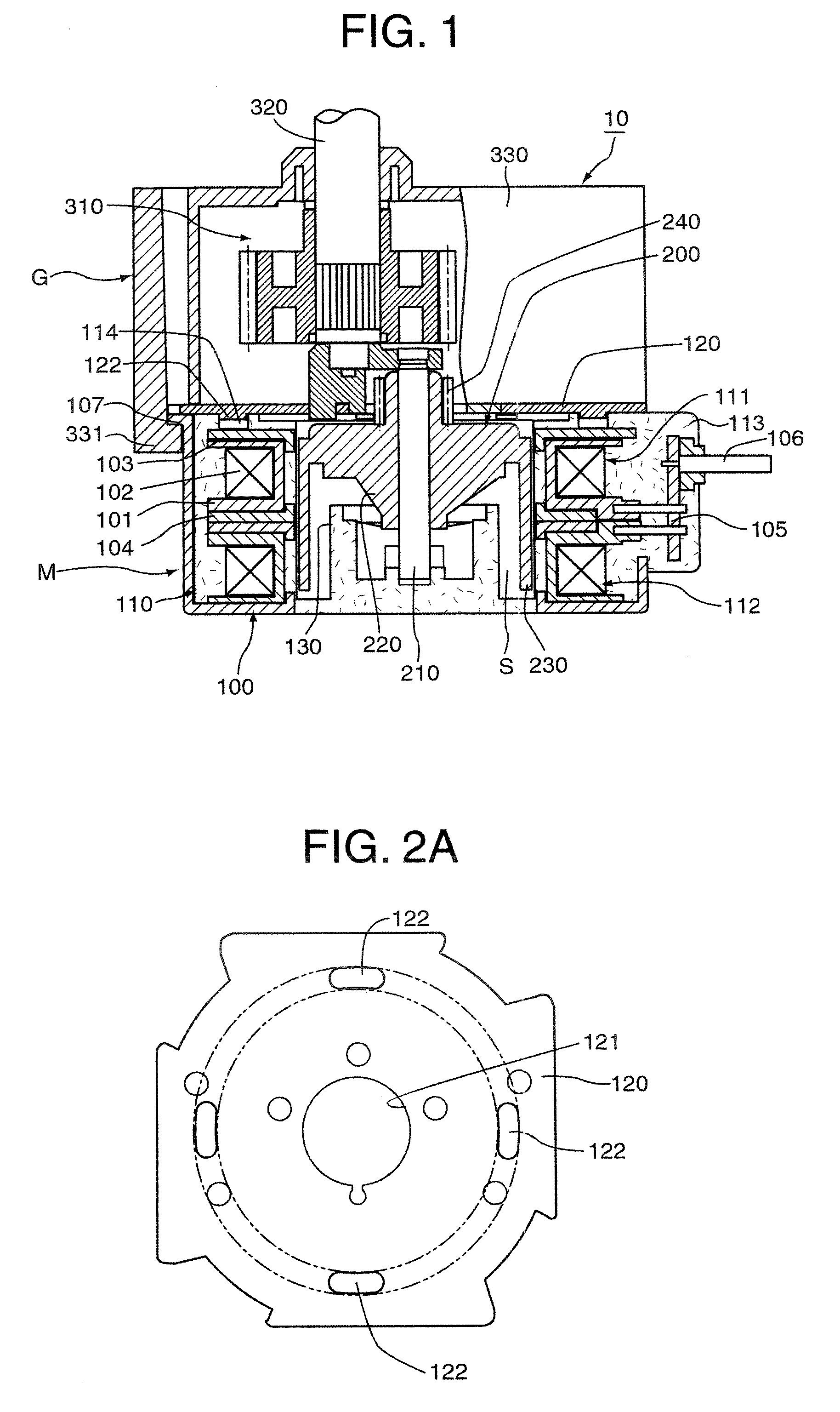
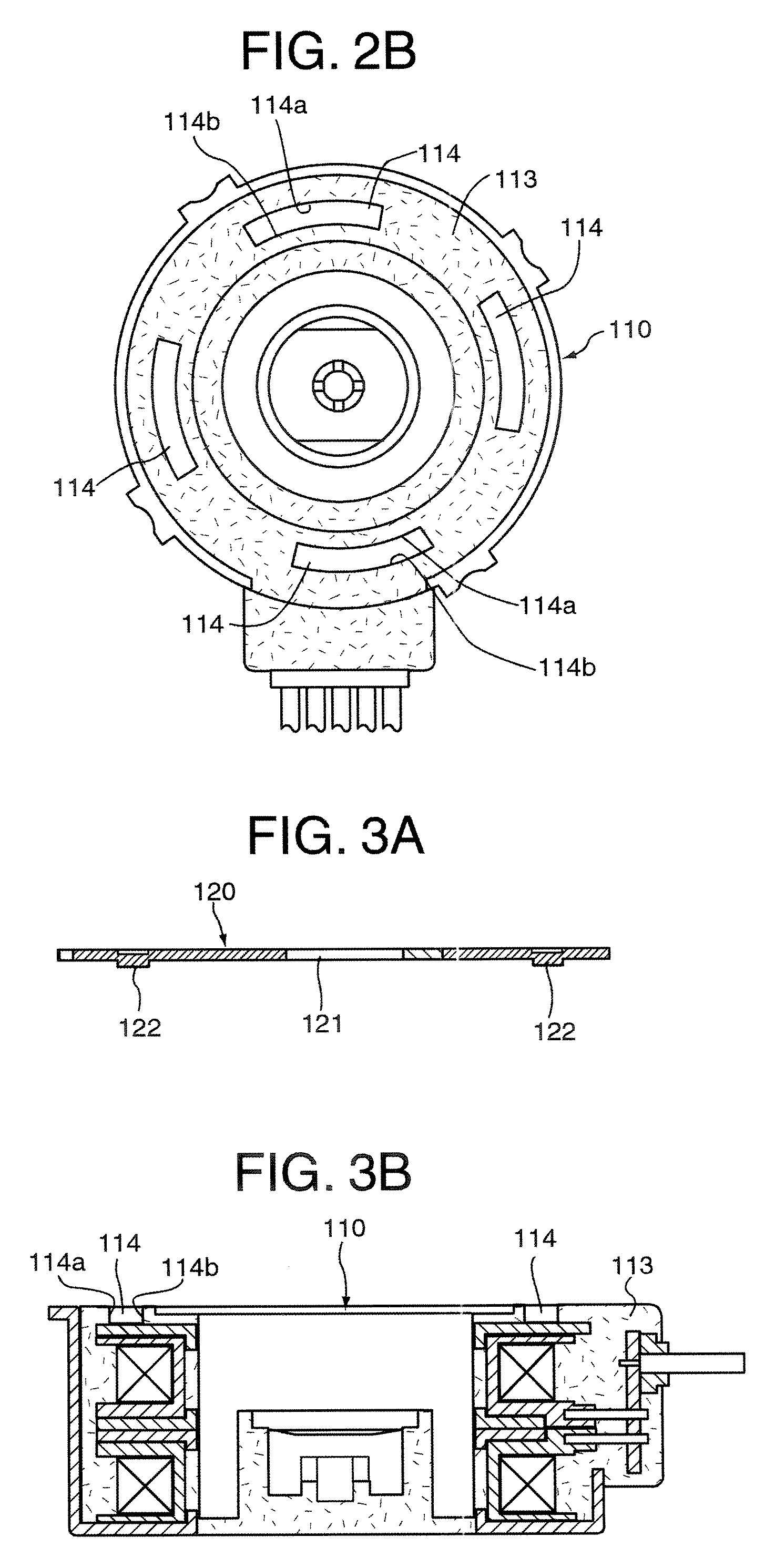
[0057]FIGS. 1, 2A, 2B, 3A and 3B show a construction of a motor to which the motor assembly structure as the first embodiment according to the positioning structure between parts of different materials of the present invention is applied, FIG. 1 is a sectional view of the whole motor containing a speed reducer, FIG. 2A is a plan view of the front cover of the motor shown in FIG. 1, FIG. 2B is a plan view of the stator assembly of the motor shown in FIG. 1, FIG. 3A is a sectional view of the front cover of the motor shown in FIG. 1, and FIG. 3B is a sectional view of the stator assembly of the motor shown in FIG. 1.

[0058] As shown in FIG. 1, a motor 10 of the first embodiment generally consists of a motor body M and a speed reducer G. The motor body M is provided with a stator 100 and a rotor 200. The stator 100 is provided with a stator assembly 110 and a front cover 120. The stator assembly 110 is constructed by cascading first and second unit stators 111 and 112 ...

Example

Second Embodiment

[0070]FIGS. 7A through 7C are sectional views showing the motor assembly structure according to the second embodiment of the positioning structure between parts of different materials of the present invention. FIG. 7A shows a stator assembly, FIG. 7B shows a casing, and FIG. 7C shows an assembling structure of the both parts.

[0071] A stator assembly 310 is constructed by cascading two unit stators 311 and 312 as with the first embodiment. Resin-made projections 313 are formed at the bottom of the lower unit stator 312. On the other hand, a cup-shaped casing 320 is made of metal and a groove (or a through hole) 321 to which the projections 313 are fitted are formed on a bottom wall. Three or more projections 313 are formed on a circle whose center is coincident with the rotation center as the reference point. The grooves 321 are formed corresponding to the projections 313.

[0072] According to the second embodiment, even if the positions of the projections 313 of th...

Example

Third Embodiment

[0074]FIG. 9 is a sectional view showing the assembly structure of a mold pinion and a hollow shaft according to a third embodiment of the positioning structure between parts of different materials of the present invention. The mold pinion 610 is made of resin. A gear 611 is formed at the tip of the mold pinion 610 and a groove 612 is formed on the base portion around the whole circle. The hollow pipe 620 is formed as a cylinder and the tip thereof has a function of a projection 621. Thickness of the tip portion may be thinner than the other portion.

[0075] In the example of FIG. 9, the reference point is coincident with the rotation centers of the mold pinion 610 and the hollow pipe 620. When the projection 621 is inserted into the groove 612 of the pinion 610 at a normal temperature, the projection 621 contacts the inner and outer wall surfaces of the groove 621, and thereby, the both parts are fixed. When the temperature Increases, the resin-made pinion 610 is ex...


PUM

PropertyMeasurementUnit
Structureaaaaaaaaaa
Widthaaaaaaaaaa

Abstract

A first part formed of a first material is positioned to a second part formed of a second material, which is different from the first material in degree of modification due to environmental variation, by contacting surfaces of the first and second parts. At least three projections are formed on the contact surface of the first part along a circle whose center is coincident with a reference point. Grooves are formed on the contact surface of the second part so that the respective projections are fitted therein and that have wall surfaces to which the projections can contact at the inner and outer sides of the projections. The width of the grooves is determined so that the projections contact the inner or outer wall surface of the grooves even when the first and second parts deform in different degrees due to environmental variation.

Description

BACKGROUND OF THE INVENTION [0001] The present invention relates to a positioning structure between different materials such as resin and metal that are different in degree of modification due to environmental variation. The present invention further relates to a motor assembly structure that uses the positioning structure. [0002] A mold motor, whose stator is molded of resin, has been previously used in order to improve chemical resistance and insulation. A mold motor is disclosed in Japanese unexamined patent publication JP2002-218720A, for example. [0003] In one type of mold motors, a metal front cover is fixed to a resin-molded stator assembly, and a rotor is rotatably supported by bearings mounted to the front cover. [0004]FIG. 10A, FIG. 10B, FIG. 11 and FIG. 12 show a conventional example of an assembly structure of such a mold motor. FIG. 10A is a plan view of a metal front cover, FIG. 10B is a plan view of a resin-molded stator assembly, FIG. 11 is a sectional view of the fr...

Claims


Application Information

Patent Timeline
IPC IPC(8): H02K5/00H02K15/00
CPCH02K1/145H02K3/325Y10T29/49009H02K5/163H02K7/116H02K5/08
Inventor SHIMURA, AYAKOROKUNOHE, JUNJIKANAMORI, NAOYUKI
Owner JAPAN SERVO CO LTD
Why Eureka
Try Eureka