Fencing system

a technology of fencing system and fencing rod, which is applied in the field of fencing system, can solve the problems of shortage of clips on site, relatively easy removal of the upright from the bearer, and relatively high manufacturing cos

Inactive Publication Date: 2005-04-21
KUNITZ WALTER MANFRED
View PDF14 Cites 49 Cited by
  • Summary
  • Abstract
  • Description
  • Claims
  • Application Information

AI Technical Summary

Benefits of technology

[0008] It is therefore an object of the present invention to provide a fencing system with which the aforesaid

Problems solved by technology

A disadvantage of the above fence is that, owing to the configuration of the connection, the upright is relatively easily removed from the bearer.
A disadvantage of the above fencing system is that the use of separate locking clips is cumbersome in that one has to ensure that an equal amount of clips and uprights are

Method used


Image

  • Fencing system
  • Fencing system
  • Fencing system

Examples


Embodiment Construction

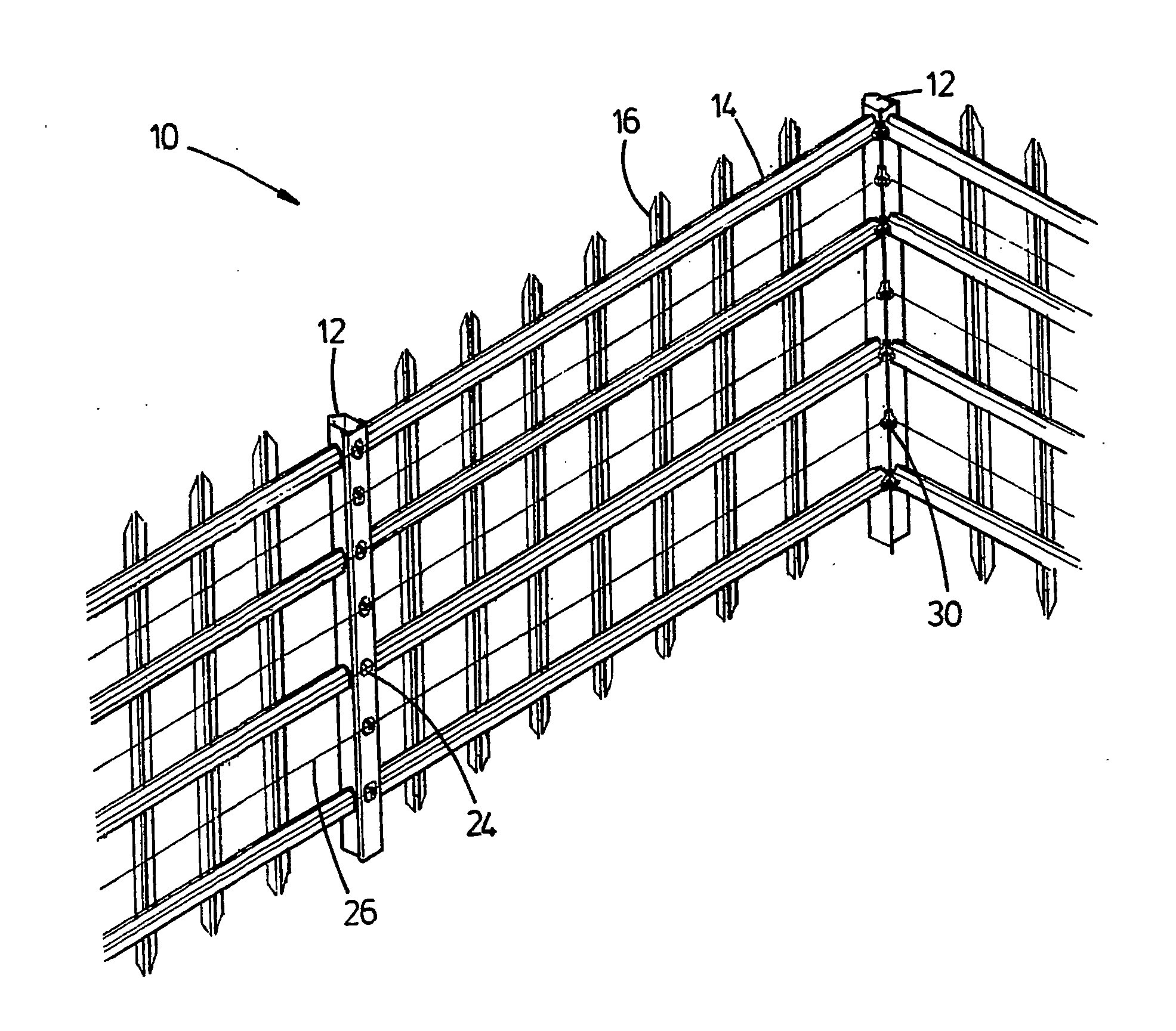
[0056] Referring to FIG. 1, a fencing system according to a preferred embodiment of the invention, is generally designated by reference numeral 10.

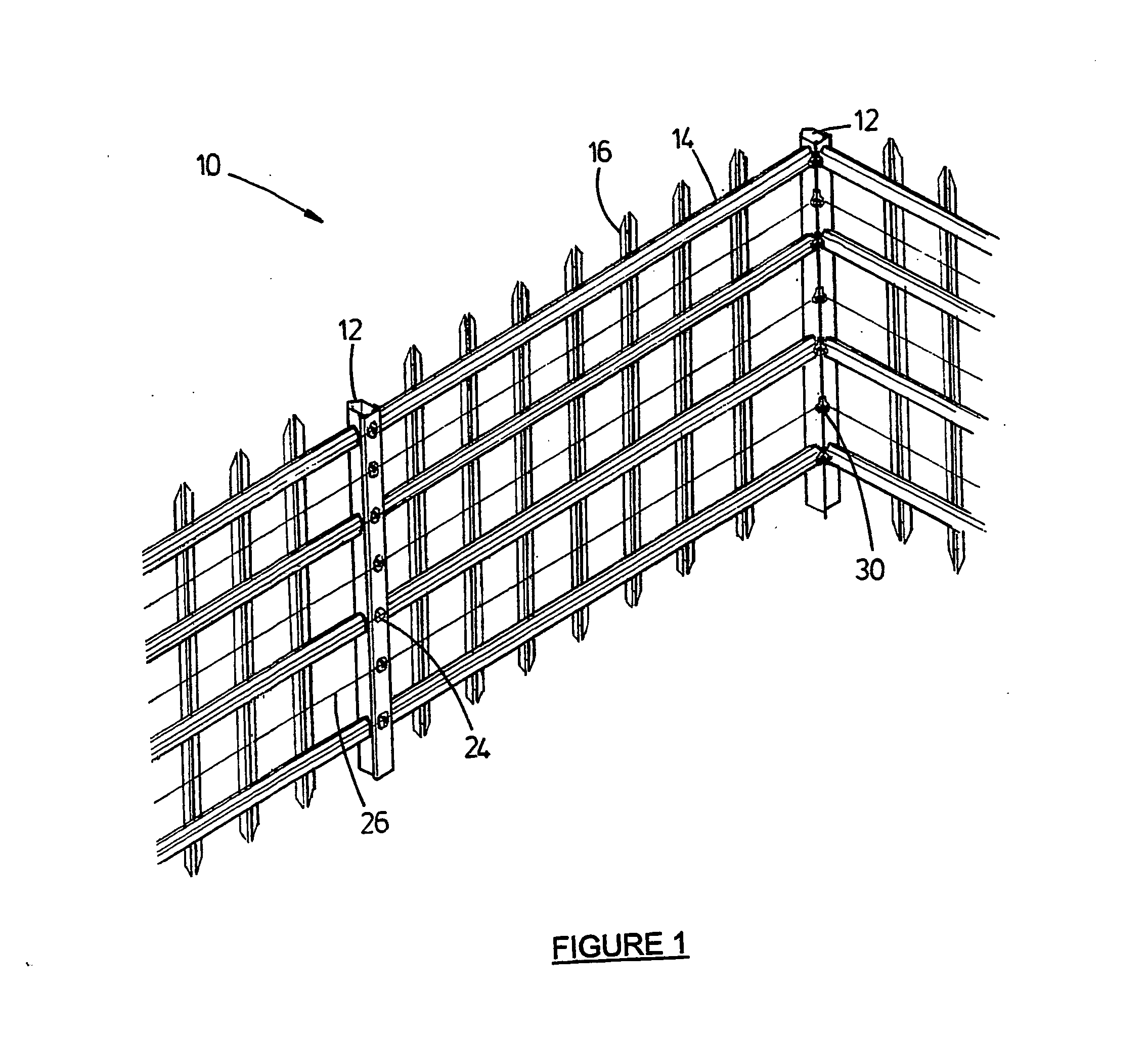
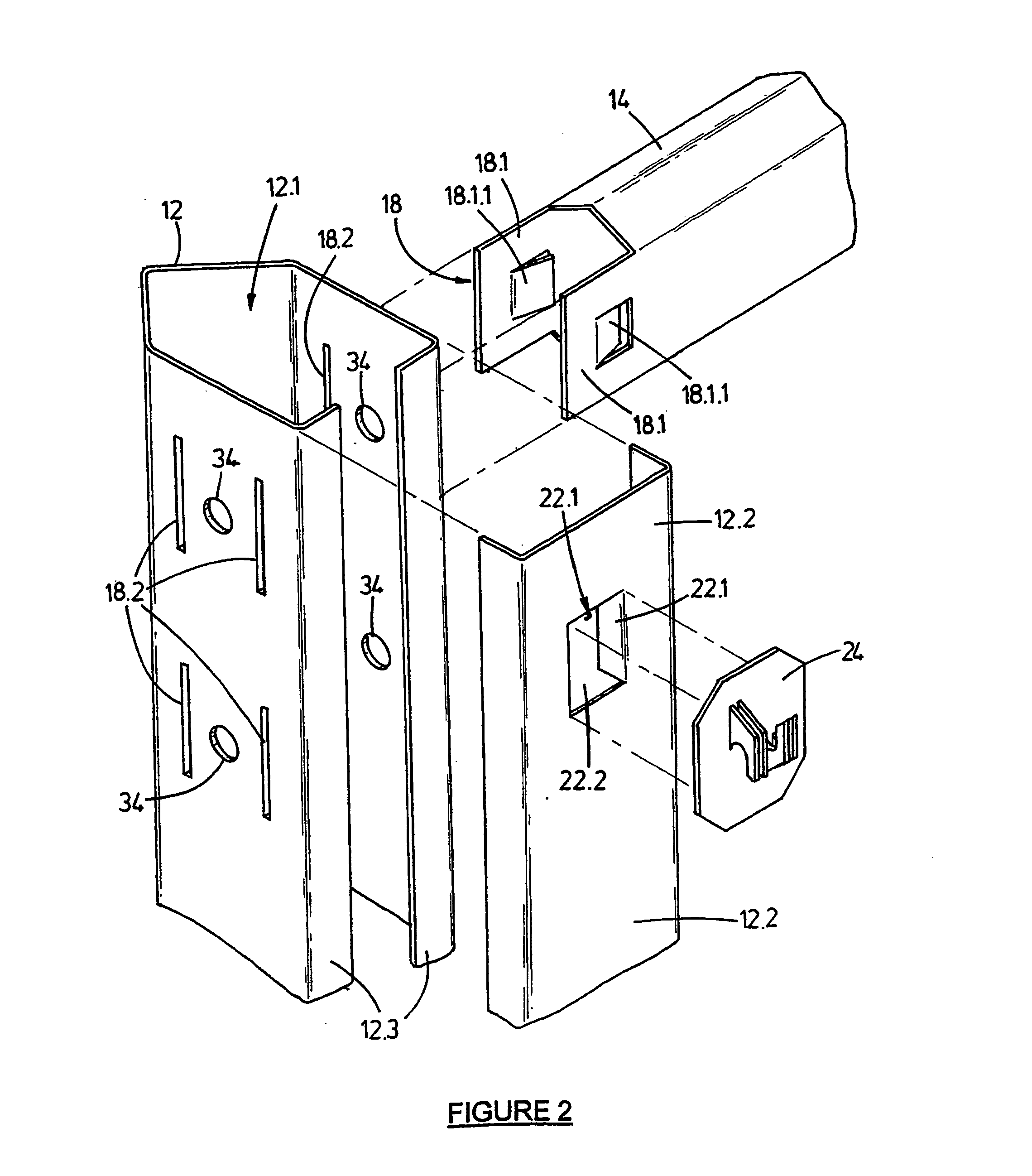
[0057] Referring further particularly to FIGS. 2 to 7 and 9, the fencing system 10 comprises a plurality of spaced apart parallel extending upright posts 12; a plurality of horizontally extending bearers 14; a plurality of parallel extending uprights 16; first connecting means 18 for connecting the bearers 14 to the posts 12; and second connecting means 20 for connecting the uprights 16 to the bearers 14. The posts 12, bearers 14, and the uprights 16, are stamped and bent from sheet metal and each define an elongate channel bordered by two opposite parallel extending flanges.

[0058] The first and second connecting means (designated by reference numerals 18 and 20) generally each comprises a male formation for mating with a female formation, the male formations being deformable after the mating, to lock the bearers 14 to the posts 12 and ...


PUM


Abstract

This invention provides a fencing system (10) comprising a plurality of spaced apart parallel extending upright posts (12); a plurality of horizontally extending bearers (14); and a plurality of parallel extending uprights (16). First connecting means (18) connects the bearers (14) to the posts (12) and second connecting means (20) connects the uprights (16) to the bearers (14). Each post (12) defines an elongate channel 12.1, and is provided with a cover 12.2 connected to the post (12) by a fourth connecting means (22), for closing the channel 12.1. Posts (12) located in a central region of the fencing system (10) are adapted to receive a supporting insulator (24), for supporting an electrified conductor (26). A carrier (28) is connected to corner posts (12) by third connecting means and includes a carrier (28) with connecting formations 28.2 for connecting to an insulator (30) for carrying electrified conductors (26).

Description

INTRODUCTION AND BACKGROUND TO THE INVENTION [0001] This invention relates to a fencing system. [0002] South African patent number 99 / 0156 discloses a method of joining an upright to a bearer. Both the upright and the bearer are of channel sections and comprise a web with a flange along each edge of the web, the flanges diverging from one another in the direction away from the web. This method includes the steps of forming two spaced slots in the bearer, the slots being at an angle with respect to one another, forcing said flanges of said upright towards one another to decrease the size of the gap between them, inserting the flanges into said slots and releasing the flanges so that they spring apart. [0003] A disadvantage of the above fence is that, owing to the configuration of the connection, the upright is relatively easily removed from the bearer. [0004] South African patent number 2000 / 0700 discloses a method of constructing a fence. This method includes the steps of erecting a...

Claims


Application Information

Patent Timeline
IPC IPC(8): E04HE04H17/14
CPCE04H17/1434E04H17/143E04H17/1447
Inventor KUNITZ, WALTER MANFRED
Owner KUNITZ WALTER MANFRED
Why Eureka
Try Eureka